Cisco 2970 Hardware Installation Guide - Page 30
Catalyst 2912 XL, 2924 XL, and 2924C XL LEDs, Catalyst 2900 Series
 |
UPC - 746320852614
View all Cisco 2970 manuals
Add to My Manuals
Save this manual to your list of manuals |
Page 30 highlights
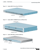
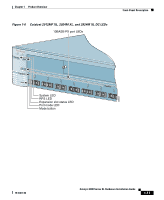
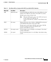
Front-Panel Description Chapter 1 Product Overview All of the LEDs described in this section except the utilization meter (UTL) are visible on the Cluster Management Suite (CMS) window and, if the switch is a cluster member, on the CMS Cluster Manager window. The Catalyst 2900 Series XL and Catalyst 3500 Series XL Software Configuration Guide describes how to use CMS to manage standalone or individual switches and how to use cluster management software to manage switch clusters]. Figure 1-5 Catalyst 2912 XL, 2924 XL, and 2924C XL LEDs 10/100 port LEDs System LED Port mode LEDs MODE 1X 2X 3X 4X 5X 6X 7X Mode RPS button LED 47288 1-10 Catalyst 2900 Series XL Hardware Installation Guide 78-6461-04
-
 1
1 -
2
-
3
-
4
-
5
-
6
-
7
-
8
-
9
-
10
-
11
-
12
-
13
-
14
-
15
-
16
-
17
-
18
-
19
-
20
-
21
-
22
-
23
-
24
-
 25
25 -
 26
26 -
 27
27 -
 28
28 -
 29
29 -
 30
30 -
 31
31 -
 32
32 -
 33
33 -
 34
34 -
 35
35 -
36
-
37
-
38
-
39
-
40
-
41
-
42
-
43
-
44
-
45
-
46
-
47
-
48
-
49
-
50
-
51
-
52
-
53
-
54
-
55
-
56
-
57
-
58
-
59
-
60
-
61
-
62
-
63
-
64
-
65
-
66
-
67
-
68
-
69
-
70
-
71
-
72
-
73
-
74
-
75
-
76
-
77
-
78
-
79
-
80
-
81
-
82
-
83
-
84
-
85
-
86
-
87
-
88
-
89
-
90
-
91
-
92
-
93
-
94
-
95
-
96
-
97
-
98
-
99
-
100
-
101
-
102
-
103
-
104
-
105
-
106
-
107
-
108
-
109
-
110
-
111
-
112
-
113
-
114
-
115
-
116
-
117
-
118
-
119
-
120
-
121
-
122
-
123
-
124
-
125
-
126
-
127
-
128
-
129
-
130
-
131
-
132
-
133
-
134
-
135
-
136
-
137
-
138
-
139
-
140
-
141
-
142
-
143
-
144
-
145
-
146
-
147
-
148
-
149
-
150
-
151
-
152
-
153
-
154
-
155
-
156
-
157
-
158
-
159
-
160
-
161
-
162
 |
 |

Chapter 1
Product Overview
Front-Panel Description
1-10
Catalyst 2900 Series XL Hardware Installation Guide
78-6461-04
All of the LEDs described in this section except the utilization meter (UTL) are
visible on the Cluster Management Suite (CMS) window and, if the switch is a
cluster member, on the CMS Cluster Manager window. The
Catalyst 2900 Series
XL and Catalyst 3500 Series XL Software Configuration Guide
describes how to
use CMS to manage standalone or individual switches and how to use cluster
management software to manage switch clusters].
Figure 1-5
Catalyst 2912 XL, 2924 XL, and 2924C XL LEDs
1X
2X
3X
4X
5X
6X
7X
1X
2X
3X
4X
5X
6X
7X
MODE
10/100 port LEDs
Mode
button
System LED
47288
RPS
LED
Port mode LEDs