Cisco 2970 Hardware Installation Guide - Page 50
Hungary, Installation Guidelines
 |
UPC - 746320852614
View all Cisco 2970 manuals
Add to My Manuals
Save this manual to your list of manuals |
Page 50 highlights
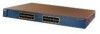
Preparing for Installation Chapter 2 Installation Hungary This equipment is a Class A product and should be used and installed properly according to the Hungarian EMC Class A requirements (MSZEN55022). Class A equipment is designed for typical commercial establishments for which special conditions of installation and protection distance are used. Figyelmeztetés a felhasználói kézikönyv számára: Ez a berendezés "A" osztályú termék, felhasználására és üzembe helyezésére a magyar EMC "A" osztályú követelményeknek (MSZ EN 55022) megfeleloen kerülhet sor, illetve ezen "A" osztályú berendezések csak megfelelo kereskedelmi forrásból származhatnak, amelyek biztosítják a megfelelo speciális üzembe helyezési körülményeket és biztonságos üzemelési távolságok alkalmazását. Installation Guidelines The switch can be installed on a table or shelf, in a rack, or on a wall. Before installing the switch, first verify that the switch is operational by powering it on and running POST. Follow the procedures in the "Powering On the Switch and Running POST" section on page 2-24. Caution There are no serviceable parts inside the unit. Removing screws, cover, or otherwise dismantling the unit voids the warranty. Warning Unplug the power cord before you work on a system that does not have an on/off switch. When determining where to place the switch, be sure to observe these guidelines: • For 10/100 ports, cable lengths from the switch to connected devices are up to 328 feet (100 meters). • For 100BASE-FX ports, cable lengths from the switch to connected devices are up to 1351 feet (412 meters) for half-duplex connections and less than 6561 feet (2 kilometers) for full-duplex connections. Catalyst 2900 Series XL Hardware Installation Guide 2-6 78-6461-04
-
 1
1 -
2
-
3
-
4
-
5
-
6
-
7
-
8
-
9
-
10
-
11
-
12
-
13
-
14
-
15
-
16
-
17
-
18
-
19
-
20
-
21
-
22
-
23
-
24
-
25
-
26
-
27
-
28
-
29
-
30
-
31
-
32
-
33
-
34
-
35
-
36
-
37
-
38
-
39
-
40
-
41
-
42
-
43
-
44
-
 45
45 -
 46
46 -
 47
47 -
 48
48 -
 49
49 -
 50
50 -
 51
51 -
 52
52 -
 53
53 -
 54
54 -
 55
55 -
56
-
57
-
58
-
59
-
60
-
61
-
62
-
63
-
64
-
65
-
66
-
67
-
68
-
69
-
70
-
71
-
72
-
73
-
74
-
75
-
76
-
77
-
78
-
79
-
80
-
81
-
82
-
83
-
84
-
85
-
86
-
87
-
88
-
89
-
90
-
91
-
92
-
93
-
94
-
95
-
96
-
97
-
98
-
99
-
100
-
101
-
102
-
103
-
104
-
105
-
106
-
107
-
108
-
109
-
110
-
111
-
112
-
113
-
114
-
115
-
116
-
117
-
118
-
119
-
120
-
121
-
122
-
123
-
124
-
125
-
126
-
127
-
128
-
129
-
130
-
131
-
132
-
133
-
134
-
135
-
136
-
137
-
138
-
139
-
140
-
141
-
142
-
143
-
144
-
145
-
146
-
147
-
148
-
149
-
150
-
151
-
152
-
153
-
154
-
155
-
156
-
157
-
158
-
159
-
160
-
161
-
162
 |
 |
