Cisco 2970 Hardware Installation Guide - Page 69
Connecting to DC Power, Preparing for Installation
 |
UPC - 746320852614
View all Cisco 2970 manuals
Add to My Manuals
Save this manual to your list of manuals |
Page 69 highlights
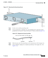
Chapter 2 Installation Connecting to DC Power The System LED flashes green, and the RPS LED turns off. As each test runs, the port LEDs, starting with number 1, turn off. The port LEDs for ports 2 to 8 each turn off in turn as the system completes a test. When POST completes successfully, the port LEDs return to the status mode display, indicating that the switch is operational. If a test fails, the port LED associated with the test turns amber, and the system LED turns amber. If POST fails, refer to Chapter 3, "Troubleshooting," to determine a course of action. POST failures are usually fatal. Call Cisco Systems immediately if your switch does not pass POST. Connecting to DC Power To connect the Catalyst 2924M XL DC switch to a DC-input power source, follow the steps in these sections: • Preparing for Installation • Grounding the Switch • Wiring the DC-Input Power Source Preparing for Installation Follow these steps before rack-mounting and grounding the switch or wiring it to a DC-input power source. Step 1 Step 2 Unpack the shipping box, and verify its contents. In addition to the items described in the Catalyst 2900 Series XL Installation Guide, the switch is shipped with a DC terminal block plug on the switch back panel. Obtain the following necessary tools and equipment: • Ratcheting torque screwdriver with a Phillips head that exerts up to 15 pound-force inches (lbf-in.) of pressure • Panduit crimping tool with optional controlled cycle mechanism, model CT-700, CT-720, CT-920, CT-930, CT-920CH, or CT-940CH • 6-gauge copper ground wire (insulated or noninsulated) 78-6461-04 Catalyst 2900 Series XL Hardware Installation Guide 2-25
-
 1
1 -
2
-
3
-
4
-
5
-
6
-
7
-
8
-
9
-
10
-
11
-
12
-
13
-
14
-
15
-
16
-
17
-
18
-
19
-
20
-
21
-
22
-
23
-
24
-
25
-
26
-
27
-
28
-
29
-
30
-
31
-
32
-
33
-
34
-
35
-
36
-
37
-
38
-
39
-
40
-
41
-
42
-
43
-
44
-
45
-
46
-
47
-
48
-
49
-
50
-
51
-
52
-
53
-
54
-
55
-
56
-
57
-
58
-
59
-
60
-
61
-
62
-
63
-
 64
64 -
 65
65 -
 66
66 -
 67
67 -
 68
68 -
 69
69 -
 70
70 -
 71
71 -
 72
72 -
 73
73 -
 74
74 -
75
-
76
-
77
-
78
-
79
-
80
-
81
-
82
-
83
-
84
-
85
-
86
-
87
-
88
-
89
-
90
-
91
-
92
-
93
-
94
-
95
-
96
-
97
-
98
-
99
-
100
-
101
-
102
-
103
-
104
-
105
-
106
-
107
-
108
-
109
-
110
-
111
-
112
-
113
-
114
-
115
-
116
-
117
-
118
-
119
-
120
-
121
-
122
-
123
-
124
-
125
-
126
-
127
-
128
-
129
-
130
-
131
-
132
-
133
-
134
-
135
-
136
-
137
-
138
-
139
-
140
-
141
-
142
-
143
-
144
-
145
-
146
-
147
-
148
-
149
-
150
-
151
-
152
-
153
-
154
-
155
-
156
-
157
-
158
-
159
-
160
-
161
-
162
 |
 |
