Cisco 2970 Hardware Installation Guide - Page 33
RPS LED, Color, RPS Status
 |
UPC - 746320852614
View all Cisco 2970 manuals
Add to My Manuals
Save this manual to your list of manuals |
Page 33 highlights
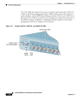
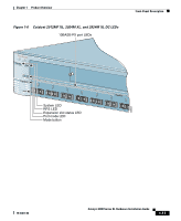
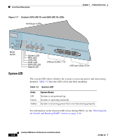
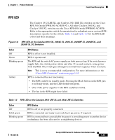
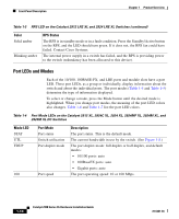
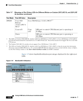
Chapter 1 Product Overview Front-Panel Description RPS LED The Catalyst 2912 LRE XL and Catalyst 2924 LRE XL switches use the Cisco RPS 300 (model PWR300-AC-RPS-N1). All other Catalyst 2900 XL and Catalyst 3500 XL switches use the Cisco RPS 600 (model PWR600-AC-RPS). Refer to the appropriate switch documentation for redundant power system (RPS) descriptions specific for the switch. Table 1-2 and Table 1-3 list the RPS LED colors and their meanings. Figure 1-8 RPS LED on the Catalyst 2912 XL, 2924C XL, 2924 XL, 2924MF XL, 2924M XL, and 2924M XL DC Switches Color Off Green Blinking green Amber RPS Status RPS is off or is not installed. RPS is operational. The RPS and the switch AC power supply are both powered up. If the switch power supply fails, the switch powers down and after 15 seconds restarts, using power from the RPS. The switch goes through its normal boot sequence when it restarts. Note This is not a recommended configuration. For more information see the "Cisco RPS Connector" section on page 1-22. RPS is connected but not functioning. • The RPS could be in standby mode. Pressing the Mode button on the RPS puts it in Ready mode, and the LED should turn green. • One of the power supplies in the RPS could have failed. • The fan in the RPS might have failed. Table 1-3 RPS LED on the Catalyst 2912 LRE XL and 2924 LRE XL Switches Color Off Solid green Blinking green RPS Status RPS is off or not properly connected. RPS is connected and ready to provide back-up power, if required. RPS is connected but is unavailable because it is providing power to another device (redundancy has been allocated to a neighboring device). 78-6461-04 Catalyst 2900 Series XL Hardware Installation Guide 1-13
-
 1
1 -
2
-
3
-
4
-
5
-
6
-
7
-
8
-
9
-
10
-
11
-
12
-
13
-
14
-
15
-
16
-
17
-
18
-
19
-
20
-
21
-
22
-
23
-
24
-
25
-
26
-
27
-
 28
28 -
 29
29 -
 30
30 -
 31
31 -
 32
32 -
 33
33 -
 34
34 -
 35
35 -
 36
36 -
 37
37 -
 38
38 -
39
-
40
-
41
-
42
-
43
-
44
-
45
-
46
-
47
-
48
-
49
-
50
-
51
-
52
-
53
-
54
-
55
-
56
-
57
-
58
-
59
-
60
-
61
-
62
-
63
-
64
-
65
-
66
-
67
-
68
-
69
-
70
-
71
-
72
-
73
-
74
-
75
-
76
-
77
-
78
-
79
-
80
-
81
-
82
-
83
-
84
-
85
-
86
-
87
-
88
-
89
-
90
-
91
-
92
-
93
-
94
-
95
-
96
-
97
-
98
-
99
-
100
-
101
-
102
-
103
-
104
-
105
-
106
-
107
-
108
-
109
-
110
-
111
-
112
-
113
-
114
-
115
-
116
-
117
-
118
-
119
-
120
-
121
-
122
-
123
-
124
-
125
-
126
-
127
-
128
-
129
-
130
-
131
-
132
-
133
-
134
-
135
-
136
-
137
-
138
-
139
-
140
-
141
-
142
-
143
-
144
-
145
-
146
-
147
-
148
-
149
-
150
-
151
-
152
-
153
-
154
-
155
-
156
-
157
-
158
-
159
-
160
-
161
-
162
 |
 |