Cisco AIR-BR350-E-K9 Hardware Installation Guide - Page 14
Key Features
 |
View all Cisco AIR-BR350-E-K9 manuals
Add to My Manuals
Save this manual to your list of manuals |
Page 14 highlights
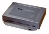
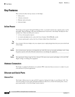
Key Features Chapter 1 Overview Key Features This section describes the key features of the bridge: • Inline power • Antenna connectors • Ethernet and serial ports • Indicator lights Inline Power The bridge receives power through the Ethernet cable, so you don't need to run a separate power cord to the bridge. Plug the Ethernet cable into the Ethernet port on the back of the bridge and plug the other end into one of three possible power sources: • A Cisco Aironet power injector • A switch with inline power, such as the Cisco Catalyst 3524-PWR-XL switch • A power patch panel, such as the Cisco Catalyst Inline Power Patch Panel Note Cisco Aironet 340 series bridges rely on a separate power supply plugged into the power port on the back of the bridge. Caution Cisco Aironet power injectors are designed for use with 350 series access points and bridges only. Using the power injector with other Ethernet-ready devices can damage the equipment. Caution The operational voltage range for Cisco Aironet 350 series access points and bridges is 24 to 60 VDC. Higher voltage can damage the equipment. Antenna Connectors The bridge is equipped with dual reverse-polarity TNC connectors that you can use to connect to your own antennas for special applications. Ethernet and Serial Ports Ethernet Port The bridge's Ethernet port accepts an RJ-45 connector, linking the bridge to your Ethernet LAN. The 350 series bridge receives power through the Ethernet cable from a switch with inline power, from a power patch panel, or from the bridge's power injector. Cisco Aironet 350 Series Bridge Hardware Installation Guide 1-2 OL-1412-01
-
 1
1 -
2
-
3
-
4
-
5
-
6
-
7
-
8
-
 9
9 -
 10
10 -
 11
11 -
 12
12 -
 13
13 -
 14
14 -
 15
15 -
 16
16 -
 17
17 -
 18
18 -
 19
19 -
20
-
21
-
22
-
23
-
24
-
25
-
26
-
27
-
28
-
29
-
30
-
31
-
32
-
33
-
34
-
35
-
36
-
37
-
38
-
39
-
40
-
41
-
42
-
43
-
44
-
45
-
46
-
47
-
48
-
49
-
50
-
51
-
52
-
53
-
54
-
55
-
56
-
57
-
58
-
59
-
60
-
61
-
62
-
63
-
64
-
65
-
66
-
67
-
68
-
69
-
70
-
71
-
72
-
73
-
74
-
75
-
76
 |
 |
