Cisco AIR-BR350-E-K9 Hardware Installation Guide - Page 38
Connecting the Serial Cable
 |
View all Cisco AIR-BR350-E-K9 manuals
Add to My Manuals
Save this manual to your list of manuals |
Page 38 highlights
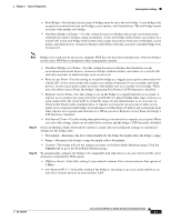
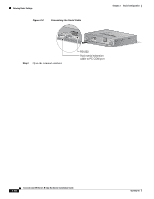
Entering Basic Settings Figure 3-3 Connecting the Serial Cable Chapter 3 Basic Configuration W I RCEILSECSOS AAICRCOE SN SETP 3O I50N STERIES RADIOAASCSTIOVCIEITTAYTHIEORNNSETTATAUCSTIVITY 5VDC SERIAL PORT LEFT SERIAL PORT ONLINE POWER ETHERNET RIGHT/PRIMARY Step 2 Open the terminal emulator. RS-232 9-pin serial extension cable to PC COM port 3-10 Cisco Aironet 350 Series Bridge Hardware Installation Guide OL-1412-01
-
 1
1 -
2
-
3
-
4
-
5
-
6
-
7
-
8
-
9
-
10
-
11
-
12
-
13
-
14
-
15
-
16
-
17
-
18
-
19
-
20
-
21
-
22
-
23
-
24
-
25
-
26
-
27
-
28
-
29
-
30
-
31
-
32
-
 33
33 -
 34
34 -
 35
35 -
 36
36 -
 37
37 -
 38
38 -
 39
39 -
 40
40 -
 41
41 -
 42
42 -
 43
43 -
44
-
45
-
46
-
47
-
48
-
49
-
50
-
51
-
52
-
53
-
54
-
55
-
56
-
57
-
58
-
59
-
60
-
61
-
62
-
63
-
64
-
65
-
66
-
67
-
68
-
69
-
70
-
71
-
72
-
73
-
74
-
75
-
76
 |
 |

3-10
Cisco Aironet 350 Series Bridge Hardware Installation Guide
OL-1412-01
Chapter 3
Basic Configuration
Entering Basic Settings
Figure 3-3
Connecting the Serial Cable
Step 2
Open the terminal emulator.
CISCO AIRONET 350
SERIES
WIRELESS ACCESS POINT
ETHERNET ACTIVITY
ASSOCIATION STATUS
RADIO ACTIVITY
SERIAL PORT
ONLINE POWER ETHERNET
LEFT
RIGHT/PRIMARY
SERIAL PORT
5VDC
9-pin serial extension
cable to PC COM port
RS-232