Cisco AIR-BR350-E-K9 Hardware Installation Guide - Page 26
Connecting the Antenna Cable, Connecting the Ethernet Cables
 |
View all Cisco AIR-BR350-E-K9 manuals
Add to My Manuals
Save this manual to your list of manuals |
Page 26 highlights
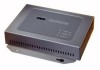
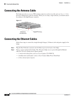
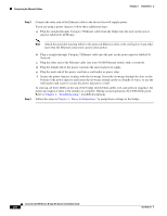
Connecting the Antenna Cable Chapter 2 Installation Connecting the Antenna Cable The bridge provides two reverse TNC antenna connectors on the rear of the unit (see Figure 2-1) for diversity configurations with two antennas. When you are using a single antenna, you should connect the antenna to the Right/Primary connector. Figure 2-1 W I RCEILSECSOS AAICRCOE SN SETP 3O I50N STERIES RADIOAASCSTIOVCIEITTAYTHIEORNNSETTATAUCSTIVITY LEFT SERIAL PORT ONLINE POWER ETHERNET RIGHT/PRIMARY Antenna connectors Right/Primary Connecting the Ethernet Cables Follow these steps to connect the straight-through Category 5 Ethernet cable and power supply to the bridge: Step 1 Step 2 Plug the RJ-45 Ethernet connector into the Ethernet port on the back of the bridge. Choose a power option for the bridge. The 350 series bridge receives power through the Ethernet cable.The 350 series bridge power options include: • A switch with inline power, such as a Cisco Catalyst 3524-PWR-XL • An inline power patch panel, such as a Cisco Catalyst Inline Power Patch Panel • A Cisco Aironet power injector Cisco Aironet 350 Series Bridge Hardware Installation Guide 2-6 OL-1412-01
-
 1
1 -
2
-
3
-
4
-
5
-
6
-
7
-
8
-
9
-
10
-
11
-
12
-
13
-
14
-
15
-
16
-
17
-
18
-
19
-
20
-
 21
21 -
 22
22 -
 23
23 -
 24
24 -
 25
25 -
 26
26 -
 27
27 -
 28
28 -
 29
29 -
 30
30 -
 31
31 -
32
-
33
-
34
-
35
-
36
-
37
-
38
-
39
-
40
-
41
-
42
-
43
-
44
-
45
-
46
-
47
-
48
-
49
-
50
-
51
-
52
-
53
-
54
-
55
-
56
-
57
-
58
-
59
-
60
-
61
-
62
-
63
-
64
-
65
-
66
-
67
-
68
-
69
-
70
-
71
-
72
-
73
-
74
-
75
-
76
 |
 |
