Cisco AIR-BR350-E-K9 Hardware Installation Guide - Page 28
To AP/Bridge, Network
 |
View all Cisco AIR-BR350-E-K9 manuals
Add to My Manuals
Save this manual to your list of manuals |
Page 28 highlights
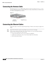
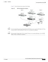
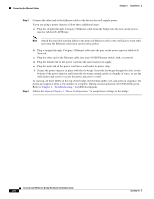
Connecting the Ethernet Cables Chapter 2 Installation Step 3 Connect the other end of the Ethernet cable to the device that will supply power. If you are using a power injector, follow these additional steps: a. Plug the straight-through, Category 5 Ethernet cable from the bridge into the port on the power injector labeled To AP/Bridge. Note Attach the provided warning labels to the powered Ethernet cable or the wall jack to warn other users that the Ethernet connection carries inline power. Step 4 b. Plug a straight-through, Category 5 Ethernet cable into the port on the power injector labeled To Network. c. Plug the other end of the Ethernet cable into your 10/100 Ethernet switch, hub, or network. d. Plug the female end of the power cord into the universal power supply. e. Plug the male end of the power cord into a wall outlet or power strip. f. Secure the power injector in place with the tie-wraps. Insert the tie-wraps through the slots on the bottom of the power injector and fasten the tie-wraps around a pole or a bundle of wires, or use the wall anchor and screw to secure the power injector to a wall. At start-up, all three LEDs on the top of the bridge slowly blink amber, red, and green in sequence; the power-up sequence takes a few minutes to complete. During normal operation, the LEDs blink green. Refer to Chapter 4, "Troubleshooting," for LED descriptions. Follow the steps in Chapter 3, "Basic Configuration," to assign basic settings to the bridge. Cisco Aironet 350 Series Bridge Hardware Installation Guide 2-8 OL-1412-01
-
 1
1 -
2
-
3
-
4
-
5
-
6
-
7
-
8
-
9
-
10
-
11
-
12
-
13
-
14
-
15
-
16
-
17
-
18
-
19
-
20
-
21
-
22
-
 23
23 -
 24
24 -
 25
25 -
 26
26 -
 27
27 -
 28
28 -
 29
29 -
 30
30 -
 31
31 -
 32
32 -
 33
33 -
34
-
35
-
36
-
37
-
38
-
39
-
40
-
41
-
42
-
43
-
44
-
45
-
46
-
47
-
48
-
49
-
50
-
51
-
52
-
53
-
54
-
55
-
56
-
57
-
58
-
59
-
60
-
61
-
62
-
63
-
64
-
65
-
66
-
67
-
68
-
69
-
70
-
71
-
72
-
73
-
74
-
75
-
76
 |
 |
