Cisco ASR1002 Quick Start Guide - Page 10
Chassis Ground Connection Installation, Step 1 - asr power requirements
 |
UPC - 882658196416
View all Cisco ASR1002 manuals
Add to My Manuals
Save this manual to your list of manuals |
Page 10 highlights
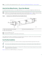
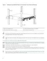
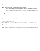
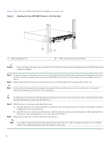
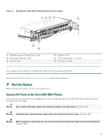
This completes the procedure for installing the cable-management brackets on a Cisco ASR 1002-F Router for a chassis rack-mount configuration. Chassis Ground Connection Installation Before you connect power or turn on power to your router, you must provide an adequate chassis ground (earth) connection for the Cisco ASR 1002-F Router. The two-hole chassis ground lug and the respective screws that ship with your Cisco ASR 1002-F Router. The following tools, equipment, and supplies are necessary to connect the system ground to the chassis: • Phillips screwdriver • Dual-lug chassis ground component (two) and respective screws (four) (shipped with the accessory kit) • Grounding wire See Figure 7 for the location of the chassis ground connector on the Cisco ASR 1002-F Router. Figure 7 Cisco ASR 1002-F Router Ground Connector Location and eUSB Panel Door 0 A/L C/A 1 A/L C/A 2 A/L C/A 3 A/L C/A STATUS 274501 1 0 2 SPA-4XOC3-POS 1 Cisco ASR 1002-F Router ground connector location 1 eUSB panel door Step 1 Step 2 Step 3 Use the wire stripper to strip one end of the AWG #6 wire approximately 0.75 inches (19.05 mm). Insert the AWG #6 wire into the wire receptacle on the ground lug. Use a manufacturer's recommended crimping tool to carefully crimp the wire receptacle around the wire; this step is required to ensure a proper mechanical connection. 10
-
 1
1 -
2
-
3
-
4
-
 5
5 -
 6
6 -
 7
7 -
 8
8 -
 9
9 -
 10
10 -
 11
11 -
 12
12 -
 13
13 -
 14
14 -
 15
15 -
16
-
17
-
18
-
19
-
20
-
21
-
22
-
23
-
24
-
25
-
26
-
27
-
28
-
29
-
30
-
31
-
32
-
33
-
34
-
35
-
36
-
37
-
38
 |
 |
