Cisco ASR1002 Quick Start Guide - Page 11
Connect the Router to the Network, Console and Auxiliary Port Cable Connections - asr ports
 |
UPC - 882658196416
View all Cisco ASR1002 manuals
Add to My Manuals
Save this manual to your list of manuals |
Page 11 highlights
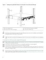
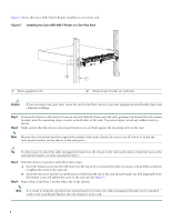
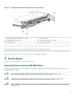
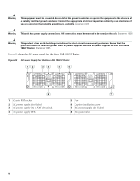
Figure 8 Attaching a Ground Lug to the Chassis Ground Connector 4 3 280034 2 1 1 Two-hole chassis ground lug 2 Ground lug screws 3 Chassis ground connector location 4 Earth ground symbol Step 4 Step 5 Step 6 Step 7 Locate the chassis ground connector on the side of your chassis. Insert the two screws through the holes in the ground lug. Use the Number 2 Phillips screwdriver to carefully tighten the screws until the ground lug is held firmly to the chassis. Do not overtighten the screws. Connect the opposite end of the ground wire to the appropriate ground point at your site to ensure an adequate chassis ground. This completes the procedure for attaching a chassis ground connection. Go to the "Connect the Router to the Network" section on page 11 for information on attaching cables. 6 Connect the Router to the Network This section provides information about cables and ports and attaching the router to the network. • Console and Auxiliary Port Cable Connections, page 11 • Management Ethernet Port Cable Connection, page 12 • Connect the Shared Port Adapter Cables, page 13 • Install the Cables Using the Cable-Management Bracket, page 14 Console and Auxiliary Port Cable Connections The Cisco ASR 1002-F Router uses RJ-45 ports for both the console port to attach a console terminal or the auxiliary port to attach a modem. The console DCE-mode port connects a console terminal and a DTE-mode auxiliary port connects a modem or other DCE device to your router. 11
-
 1
1 -
2
-
3
-
4
-
5
-
 6
6 -
 7
7 -
 8
8 -
 9
9 -
 10
10 -
 11
11 -
 12
12 -
 13
13 -
 14
14 -
 15
15 -
 16
16 -
17
-
18
-
19
-
20
-
21
-
22
-
23
-
24
-
25
-
26
-
27
-
28
-
29
-
30
-
31
-
32
-
33
-
34
-
35
-
36
-
37
-
38
 |
 |
