Cisco ASR1002 Quick Start Guide - Page 9
Attach the Cable-Management Brackets,
 |
UPC - 882658196416
View all Cisco ASR1002 manuals
Add to My Manuals
Save this manual to your list of manuals |
Page 9 highlights
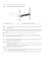
This completes the procedure for installing the chassis in a two-post rack. Proceed to the "Attach the Cable-Management Brackets" section on page 9 to continue the installation. Attach the Cable-Management Brackets The cable-management brackets for the Cisco ASR 1002-F Router contain one independent cable-management "U" feature with two screws for each bracket. For the Cisco ASR 1000 Series SIP, these brackets work in tandem with SPA cable-management brackets to allow installation and removal of adjacent SPAs without the need to remove cables. Note Make certain that the cable-management bracket "U" feature (open end) is facing upwards when you attach it to the chassis. Follow these steps to attach the cable-management brackets to both sides of the Cisco ASR 1002-F Router in the rack: Step 1 Align the cable-management bracket to the rack-mount bracket on one side of the Cisco ASR 1002-F Router. The cable-management bracket aligns to the top hole of the chassis rack-mount bracket. Note Use the package of four screws that came with the cable-management bracket package. Step 2 Insert one screw through the top screw hole of the cable-management bracket and into the chassis rack-mount bracket and tighten the screw using a Phillips screwdriver. Figure 6 Attaching the Cable-Management Brackets to the Cisco ASR 1002-F Router 0 A/L C/A 1 A/L C/A 2 A/L C/A 3 A/L C/A STATUS 274498 0 3 1 SPA-4XOC3-POS 2 1 Cable-management bracket bottom screw hole and top screw hole 2 Cable-management "U" feature 3 Chassis front rack-mount bracket Step 3 Step 4 Insert one screw through the bottom screw hole of the cable-management bracket and into the chassis rack-mount bracket and tighten the screw using a Phillips head screwdriver. Figure 6 shows the cable-management brackets attached to the chassis. Repeat Step 1 through Step 3 for the other side of the Cisco ASR 1002-F Router. 9
-
 1
1 -
2
-
3
-
 4
4 -
 5
5 -
 6
6 -
 7
7 -
 8
8 -
 9
9 -
 10
10 -
 11
11 -
 12
12 -
 13
13 -
 14
14 -
15
-
16
-
17
-
18
-
19
-
20
-
21
-
22
-
23
-
24
-
25
-
26
-
27
-
28
-
29
-
30
-
31
-
32
-
33
-
34
-
35
-
36
-
37
-
38
 |
 |
