Cisco ASR1002 Quick Start Guide - Page 18
LED Label, Color, Description, Table 2, Cisco ASR 1002-F Router DC Power Supply LEDs - power check
 |
UPC - 882658196416
View all Cisco ASR1002 manuals
Add to My Manuals
Save this manual to your list of manuals |
Page 18 highlights
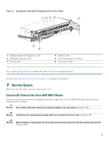
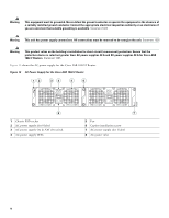
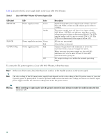
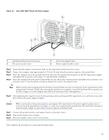
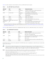
Table 2 describes the DC power supply LEDs on the Cisco ASR 1002-F Router. Table 2 Cisco ASR 1002-F Router DC Power Supply LEDs LED Label INPUT OK LED Power supply activity Color Green Amber FAN OK OUTPUT FAIL Power supply fan activity Green Red Power supply activity Red Off Description Signals that the DC power supply input voltage is greater than -43.5VDC at turn-on and remains green down to -39VDC. The power supply turns off due to low input voltage (falls below -39VDC) and indicates that there is still a voltage present (voltage on the terminal block). The LED remains amber and is active to around 20V +/- 5V. The LED is not illuminated if the input is below 15V. All fans are operational. A fan failure is detected. Output voltages below the minimum or above the maximum limits create an Output Fail alarm. When you turn the power supply on, the red LED illuminates for two to three seconds to test LED operation before going off. DC output voltages are within the normal operating range. To connect the DC power supply to a Cisco ASR 1002-F Router, follow these steps: Step 1 At the rear of the router, check that the power switch is in the Standby position on the power supply. Note The color coding of the DC-input power supply leads depends on the color coding of the DC power source at your site. Typically, green or green/yellow is used for ground. Make certain the lead color coding you choose for the DC-input power supply matches the lead color coding used at the DC power source. Warning When installing or replacing the unit, the ground connection must always be made first and disconnected last. Statement 1046 18
-
 1
1 -
2
-
3
-
4
-
5
-
6
-
7
-
8
-
9
-
10
-
11
-
12
-
 13
13 -
 14
14 -
 15
15 -
 16
16 -
 17
17 -
 18
18 -
 19
19 -
 20
20 -
 21
21 -
 22
22 -
 23
23 -
24
-
25
-
26
-
27
-
28
-
29
-
30
-
31
-
32
-
33
-
34
-
35
-
36
-
37
-
38
 |
 |
