Cisco ASR1002 Quick Start Guide - Page 22
LED Label, Color, Behavior Description, Table 3, Cisco ASR 1002-F Router LED Activity - sfp
 |
UPC - 882658196416
View all Cisco ASR1002 manuals
Add to My Manuals
Save this manual to your list of manuals |
Page 22 highlights
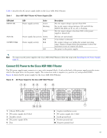
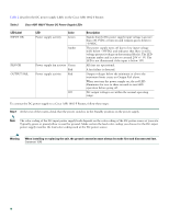
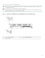
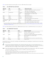
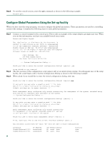
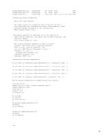
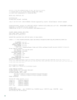
Table 3 provides information about the LEDs on the Cisco ASR 1002-F Router faceplate. Table 3 Cisco ASR 1002-F Router LED Activity LED Label LED Color Behavior Description PWR Power Solid green All power requirements are within specification. Off The router is in standby mode. STAT System status Solid green Cisco IOS has successfully booted. Yellow BOOT ROM has successfully loaded. Red System failure. MIN Minor Amber Minor alarm indicator. MAJ Major Solid red Major alarm indicator. CRIT Critical Solid red Critical alarm indicator. On at power up **Built-in 4xGE 4 LEDs total, one for each SPA SFP Port SFP Status Off Amber Green Port is not enabled. Port enabled. Problem with the Ethernet link. Port enabled and the Ethernet link is valid. **For more information about the small form-factor pluggable (SFP) transceiver modules that are compatible with Cisco ASR 1002 Built-in Gigabit Ethernet Ports (4x1GE), refer to the Modular Optics Compatibility section in the Cisco ASR 1000 Series Aggregation Services Routers SIP and SPA Hardware Installation Guide. Table 4 provides information about the Cisco ASR1002-ESP-F LEDs in the Cisco ASR 1002-F Router as the system starts. Table 4 Cisco ASR1002-ESP-F LED Activity LED Label PWR STAT LED Power Status ACTV STBY Active Standby Color Solid green Off Green Yellow Red Green None Behavior Description All power supplies are within operational limits. The router is in standby mode. Code has successfully downloaded and is operational. BOOT ROM has successfully loaded. Not booted. The integrated services processor is green when active. Always be off. During the boot process, observe the system LEDs. The STATUS LED comes on immediately as amber, then turns to green when the Cisco IOS is booted. Note The system boots differently depending on the configuration that ships with your system. The display below is a snapshot of messages that are output on the console of the Cisco ASR 1002-F Router system after power-up and during IOS booting. This is only an example of what you might see from any Cisco ASR 1000 Series Router. Step 4 Observe the initialization process. When the system boot is complete (a few seconds), the Cisco ASR 1002-F integrated route processor begins to initialize. The console screen displays a script and system banner. ASR 1002-F-16-rp0-rommon 2 >boot bootflash:asr1000rp1-advipservicesk9.v122_33_xn_asr_rls0_throttle_20080114_045627.bin Located asr1000rp1-advipservicesk9.v122_33_xn_asr_rls0_throttle_20080114_045627.bin Image size 218869964 inode num 18, bks cnt 53436 blk size 8*512 22
-
 1
1 -
2
-
3
-
4
-
5
-
6
-
7
-
8
-
9
-
10
-
11
-
12
-
13
-
14
-
15
-
16
-
 17
17 -
 18
18 -
 19
19 -
 20
20 -
 21
21 -
 22
22 -
 23
23 -
 24
24 -
 25
25 -
 26
26 -
 27
27 -
28
-
29
-
30
-
31
-
32
-
33
-
34
-
35
-
36
-
37
-
38
 |
 |