Cisco ASR1002 Quick Start Guide - Page 19
Step 2, Caution, Cisco ASR 1002-F Router DC Power Supply
 |
UPC - 882658196416
View all Cisco ASR1002 manuals
Add to My Manuals
Save this manual to your list of manuals |
Page 19 highlights
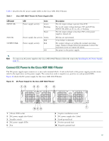
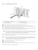
Figure 15 Cisco ASR 1002-F Router DC Power Supply 32 4 OUTPUT INPUT FAN FAIL OK OK TAotonhlledisceopu-noennwniteeemcrrgtiisgoizuhneptspthhmlayeuvcuesotnnmbitn.eoerrceetimtohnoa.vned -48V/-60V 16A 280290 1 1 Earth ground lead service loop area 2 DC power positive lead 3 DC power negative lead 4 Power supply Standby switch Step 2 Step 3 Step 4 Step 5 Ensure that the negative and positive leads are disconnected from the site power source. Using a wire stripper, strip approximately 0.55 inch (14 mm) from the positive, negative, and ground leads. Insert the stripped end of the ground lead all the way into the ground lead receptacle on the DC-input power supply, and tighten the receptacle screw using a 3.5 mm flat-blade screwdriver. Insert the stripped end of the positive lead all the way into the positive lead receptacle and tighten the receptacle screw using the same 3.5 mm flat-blade screwdriver. Repeat this step for the negative lead. Note Make sure the entire stripped end of each lead is inserted all the way into its receptacle. If any exposed wire at the stripped end of a lead is visible after inserting the lead into its receptacle, remove the lead from the receptacle, use the wire stripper to cut the stripped end of the lead, and repeat Step 3 through Step 5. Step 6 After tightening the receptacle screw for the ground, positive, and negative DC-input leads, use a cable tie to secure the three leads to the power supply faceplate. Caution When securing the earth ground, positive, and negative DC-input leads to the power supply faceplate, leave a service loop in the ground lead, (see Figure 15, item 1), to ensure that the ground lead is the last lead to disconnect from the power supply if a great deal of strain is placed on all three leads. Step 7 Step 8 Step 9 Connect the ground, positive, and negative leads to the power source. Turn on the branch source breaker. Place the Standby switch in the On (|) position. This completes the procedure for connecting DC-input power. 19
-
 1
1 -
2
-
3
-
4
-
5
-
6
-
7
-
8
-
9
-
10
-
11
-
12
-
13
-
 14
14 -
 15
15 -
 16
16 -
 17
17 -
 18
18 -
 19
19 -
 20
20 -
 21
21 -
 22
22 -
 23
23 -
 24
24 -
25
-
26
-
27
-
28
-
29
-
30
-
31
-
32
-
33
-
34
-
35
-
36
-
37
-
38
 |
 |
