Cisco ASR1002 Quick Start Guide - Page 34
Installing the DC Power Supply
 |
UPC - 882658196416
View all Cisco ASR1002 manuals
Add to My Manuals
Save this manual to your list of manuals |
Page 34 highlights
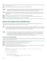
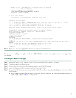
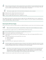
Step 7 Replace the DC power supply within five minutes or the system will shutdown. You have completed the procedure for removing a DC power supply from the Cisco ASR 1002-F Router. Installing the DC Power Supply This section provides information about replacing a DC power supply in the Cisco ASR 1002-F Router. Note The color coding of the DC-input power supply leads depends on the color coding of the DC power source at your site. Typically, green or green/yellow is used for ground. Make certain the lead color coding you choose for the DC-input power supply matches lead color coding used at the DC power source. Figure 20 Cisco ASR 1002-F Router Terminal Block -48V/-60V 16A 280291 1 Negative lead 2 Positive lead 3 Earth ground symbol Warning Never install an AC power module and a DC power module in the same chassis. Statement 1050 Warning Installation of the equipment must comply with local and national electrical codes. Statement 1074 Step 1 Step 2 Step 3 Step 4 At the rear of the router, check that the power supply Standby switch is in the Standby position. Ensure that the negative and positive leads are disconnected from the site power source and the circuit breaker is turned off. Insert a DC power supply in power supply slot 0 or power supply slot 1 until it is full seated. Using a wire stripper, strip approximately 0.55 inch (14 mm) from the negative, positive, and ground lead. 34
-
 1
1 -
2
-
3
-
4
-
5
-
6
-
7
-
8
-
9
-
10
-
11
-
12
-
13
-
14
-
15
-
16
-
17
-
18
-
19
-
20
-
21
-
22
-
23
-
24
-
25
-
26
-
27
-
28
-
 29
29 -
 30
30 -
 31
31 -
 32
32 -
 33
33 -
 34
34 -
 35
35 -
 36
36 -
 37
37 -
 38
38
 |
 |
