Cisco SRW2024P User Guide - Page 11
SRW2016 - switch
 |
UPC - 745883571000
View all Cisco SRW2024P manuals
Add to My Manuals
Save this manual to your list of manuals |
Page 11 highlights
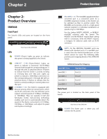
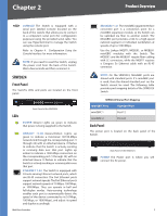
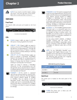
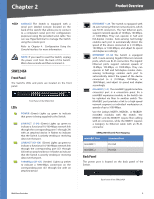
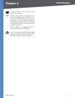
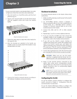
Chapter 2 Product Overview CONSOLE The Switch is equipped with a serial port labeled Console (located on the back of the switch) that allows you to connect to a computer's serial port (for configuration purposes) using the provided serial cable. You can use HyperTerminal to manage the Switch using the console port. Refer to Chapter 4: Configuration Using the Console Interface for more information. NOTE: If you need to reset the Switch, unplug the power cord from the back of the Switch. Wait a few seconds and then reconnect it. SRW2016 Front Panel The Switch's LEDs and ports are located on the front panel. Front Panel of the SRW2016 LEDs POWER (Green) Lights up green to indicate that power is being supplied to the Switch. LINK/ACT (1-16) (Green) Lights up green to indicate a functional 10/100-Mbps network link through the corresponding port (1 through 16) with an attached device. It flashes to indicate that the Switch is actively sending or receiving data over that port. Gigabit (1-16) (Amber) Lights up amber to indicate a 1000-Mbps connection on the corresponding port (1 through 16) with an attached device. ETHERNET 1-16 The Switch is equipped with 16 auto-sensing, Ethernet network ports, which use RJ-45 connectors. The Fast Ethernet ports support network speeds of 10 Mbps, 100 Mbps, or 1000 Mbps. They can operate in half and full-duplex modes. Auto-sensing technology enables each port to automatically detect the speed of the device connected to it (10 Mbps, 100 Mbps, or 1000 Mbps), and adjust its speed and duplex accordingly. WebView Switches MiniGBIC (1-2) The miniGBIC (gigabit interface converter) port is a connection point for a miniGBIC expansion module, so the Switch can be uplinked via fiber to another switch. The MiniGBIC port provides a link to a high-speed network segment or individual workstation at speeds of up to 1000 Mbps. Use the Linksys MGBT1, MGBSX1, or MGBLH1 miniGBIC modules with the Switch. The MGBSX1 and the MGBLH1 require fiber cabling with LC connectors, while the MGBT1 requires a Category 5e Ethernet cable with an RJ-45 connector. NOTE: On the SRW2016, MiniGBIC ports are shared with standard ports. If a miniGBIC port is used, then the shared standard port on the Switch cannot be used. The following table provides port mapping details of the SRW2016 Switch. SRW2016 Shared Port Mapping miniGBIC Port miniGBIC 1 miniGBIC 2 Standard Port Port 8 Port 16 The Back Panel The power port is located on the back panel of the Switch. Back Panel of the SRW2016 POWER The Power port is where you will connect the AC power. CONSOLE The Switch is equipped with a serial port labeled Console (located on the back of the switch) that allows you to connect to a computer's serial port (for configuration purposes) using the provided serial cable. You can use HyperTerminal to manage the Switch using the console port. Refer to Chapter 4: Configuration Using the Console Interface for more information. 4
-
 1
1 -
2
-
3
-
4
-
5
-
 6
6 -
 7
7 -
 8
8 -
 9
9 -
 10
10 -
 11
11 -
 12
12 -
 13
13 -
 14
14 -
 15
15 -
 16
16 -
17
-
18
-
19
-
20
-
21
-
22
-
23
-
24
-
25
-
26
-
27
-
28
-
29
-
30
-
31
-
32
-
33
-
34
-
35
-
36
-
37
-
38
-
39
-
40
-
41
-
42
-
43
-
44
-
45
-
46
-
47
-
48
-
49
-
50
-
51
-
52
-
53
-
54
-
55
-
56
-
57
-
58
-
59
-
60
-
61
-
62
-
63
-
64
-
65
-
66
-
67
-
68
-
69
-
70
-
71
-
72
-
73
-
74
-
75
-
76
-
77
-
78
-
79
-
80
-
81
-
82
-
83
-
84
-
85
-
86
-
87
-
88
-
89
-
90
-
91
-
92
-
93
-
94
-
95
-
96
 |
 |