Cisco SRW2024P User Guide - Page 27
Advanced Configuration - vlan
 |
UPC - 745883571000
View all Cisco SRW2024P manuals
Add to My Manuals
Save this manual to your list of manuals |
Page 27 highlights
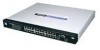
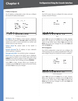
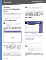
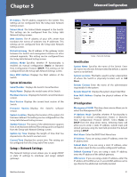
Chapter 5 Advanced Configuration Chapter 5: Advanced Configuration Overview This chapter describes the features included in the Webbased Utility. All of the features shown in this chapter, unless specifically identified, are included in all of the WebView Switches. The screen images were taken from the SRW2048 Switch. Additional features for specific Switches are noted. The SRW224G4, SRW248G4, SRW2016, and SRW2024 Switches may not support all functions. Accessing the Web-based Utility NOTE: The Web-based Utility is optimized for viewing with a screen resolution of 1024 x 768. Internet Explorer version 5.5 or above is recommended. Open your web browser and enter 192.168.1.254 into the Address field. Press the Enter key and the login screen appears. NOTE: After configuring values using the Webbased Utility, you may be required to refresh the page to see the updated configuration. The first screen that appears is the Setup Summary screen. Twelve main tabs are accessible from the Web-based Utility: Setup, Port Management, VLAN Management, Statistics, ACL, Security, QoS (Quality of Service), Spanning Tree, Multicast, SNMP, Admin, and Logout. Click one of the main tabs to view additional tabs. Setup > Summary The Summary screen provides device and system information about the Switch. Login Screen NOTE: The default IP address of the device is 192.168.1.254. If you have modified this address, enter the correct IP address. The device should be on the same subnet as the management station used to configure the device. The first time you open the Web-based Utility, enter admin in the User Name field, and leave the Password field blank. Click the OK button. For security purposes, it is recommended that you set a new password on the System Password screen. the System Password screen. WebView Switches Setup > Summary At the top of the Summary screen, an image of the Switch's front panel provides the following color-coded status information for the Switch's Ethernet ports: Green Indicates a connection. Grey Indicates no connection. Orange Indicates the port has been closed down by the administrator. When you click a port's LED, the statistics for that port are displayed. NOTE: The port colors in the Summary screen are not related to the colors of the LEDs on the Switch's ports. The port LEDs display different status information, as described in Chapter 2: Product Overview. Device Information System Name Displays the name for the Switch, if one has been entered on the Setup tab's Network Settings screen. 20
-
 1
1 -
2
-
3
-
4
-
5
-
6
-
7
-
8
-
9
-
10
-
11
-
12
-
13
-
14
-
15
-
16
-
17
-
18
-
19
-
20
-
21
-
 22
22 -
 23
23 -
 24
24 -
 25
25 -
 26
26 -
 27
27 -
 28
28 -
 29
29 -
 30
30 -
 31
31 -
 32
32 -
33
-
34
-
35
-
36
-
37
-
38
-
39
-
40
-
41
-
42
-
43
-
44
-
45
-
46
-
47
-
48
-
49
-
50
-
51
-
52
-
53
-
54
-
55
-
56
-
57
-
58
-
59
-
60
-
61
-
62
-
63
-
64
-
65
-
66
-
67
-
68
-
69
-
70
-
71
-
72
-
73
-
74
-
75
-
76
-
77
-
78
-
79
-
80
-
81
-
82
-
83
-
84
-
85
-
86
-
87
-
88
-
89
-
90
-
91
-
92
-
93
-
94
-
95
-
96
 |
 |