Cisco SRW2024P User Guide - Page 16
Hardware Installation, Configuring the Switch - ports damaged
 |
UPC - 745883571000
View all Cisco SRW2024P manuals
Add to My Manuals
Save this manual to your list of manuals |
Page 16 highlights
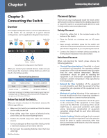
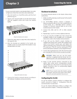
Chapter 3 Connecting the Switch To rack-mount the Switch in any standard 482.6-mm wide, 1U high rack, follow the instructions described below. 1. Place the Switch on a hard flat surface with the front panel facing you. 2. Attach a rack-mount bracket to one side of the Switch with the supplied screws and secure the bracket tightly. Attach the Brackets to the Switch 3. Follow the same steps to attach the other bracket to the opposite side. 4. After the brackets are attached to the Switch, use suitable screws to securely attach the brackets to any standard 482.6-mm rack. Mount the Switch in the Rack 5. Connect the Switch to network devices according to the Hardware Installation instructions below. Hardware Installation To connect network devices to the Switch, follow these instructions: 1. Make sure all the devices you will connect to the Switch are powered off. 2. For 10/100-Mbps devices, connect a Category 5 Ethernet network cable to one of the numbered ports on the Switch. For a 1000-Mbps device, connect a Category 5e Ethernet network cable to one of the numbered ports on the Switch. 3. Connect the other end to a PC or other network device. 4. Repeat steps 2 and 3 to connect additional devices. 5. If you are using the miniGBIC port, then connect the miniGBIC module to the miniGBIC port. For detailed instructions, refer to the module's documentation. 6. If you will use the Switch's console interface to configure the Switch, then connect the supplied serial cable to the Switch's Console port, and tighten the captive retaining screws. Connect the other end to your PC's serial port. (This PC must be running the VT100 terminal emulation software, such as HyperTerminal.) 7. Connect the supplied power cord to the Switch's power port, and plug the other end into an electrical outlet. WARNING: Make sure you use the power cord that is supplied with the Switch. Use of a different power cord could damage the Switch. 8. Power on the network devices connected to the Switch. Each active port's corresponding Link/Act LED will light up on the Switch. If a port has an active Gigabit connection, then its corresponding Gigabit LED will also light up. NOTE: If you need to reset the Switch, unplug the power cord from the back of the Switch. Wait a few seconds and then reconnect it. Configuring the Switch To use the Switch's console interface to configure the Switch, proceed to Chapter 4: Configuration Using the Console Interface for directions. To use the Switch's Web-based Utility to configure the Switch, proceed to Chapter 5: Advanced Configuration. WebView Switches 9
-
 1
1 -
2
-
3
-
4
-
5
-
6
-
7
-
8
-
9
-
10
-
 11
11 -
 12
12 -
 13
13 -
 14
14 -
 15
15 -
 16
16 -
 17
17 -
 18
18 -
 19
19 -
 20
20 -
 21
21 -
22
-
23
-
24
-
25
-
26
-
27
-
28
-
29
-
30
-
31
-
32
-
33
-
34
-
35
-
36
-
37
-
38
-
39
-
40
-
41
-
42
-
43
-
44
-
45
-
46
-
47
-
48
-
49
-
50
-
51
-
52
-
53
-
54
-
55
-
56
-
57
-
58
-
59
-
60
-
61
-
62
-
63
-
64
-
65
-
66
-
67
-
68
-
69
-
70
-
71
-
72
-
73
-
74
-
75
-
76
-
77
-
78
-
79
-
80
-
81
-
82
-
83
-
84
-
85
-
86
-
87
-
88
-
89
-
90
-
91
-
92
-
93
-
94
-
95
-
96
 |
 |
