Cisco SRW2024P User Guide - Page 15
Connecting the Switch - specifications
 |
UPC - 745883571000
View all Cisco SRW2024P manuals
Add to My Manuals
Save this manual to your list of manuals |
Page 15 highlights
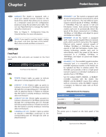
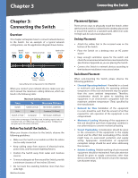
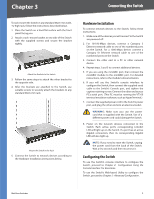
Chapter 3 Connecting the Switch Chapter 3: Connecting the Switch Overview This chapter will explain how to connect network devices to the Switch. For an example of a typical network configuration, see the application diagram shown below. Cable/DSL Internet Modem Router Wireless Access Point Server Uplink via Fiber to Switch 10/100/1000 10/100 Desktop Notebook Typical Network Configuration for the SRW2048 When you connect your network devices, make sure you don't exceed the maximum cabling distances, which are listed in the following table: Maximum Cabling Distances From To Maximum Distance Switch Switch or Hub 100 meters (328 feet) Hub Hub 5 meters (16.4 feet) Switch or Hub Computer 100 meters (328 feet) ††A hub refers to any type of 100-Mbps hub, including regular hubs and stackable hubs. A 10-Mbps hub connected to another 10-Mbps hub can span up to 100 meters (328 feet). Before You Install the Switch... When you choose a location for the Switch, observe the following guidelines: •• Make sure the Switch is accessible and that the cables can be easily connected. •• Keep cabling away from sources of electrical noise, power lines, and fluorescent lighting fixtures. •• Position the Switch away from water and moisture sources. •• To ensure adequate air flow around the Switch, provide a minimum clearance of two inches (50 mm). •• Do not stack free-standing Switches more than four units high. WebView Switches Placement Options There are two ways to physically install the Switch, either set the Switch on its four rubber feet for desktop placement or mount the switch in a standard-sized, 482.6-mm wide, 1U-high rack for rack-mount placement. Desktop Placement •• Attach the rubber feet to the recessed areas on the bottom of the Switch. •• Place the Switch on a desktop near an AC power source. •• Keep enough ventilation space for the switch and check the environmental restrictions mentioned in the Specifications Appendix as you are placing the Switch. •• Connect the Switch to network devices according to the Hardware Installation instructions below. Rack-Mount Placement When rack-mounting the Switch, please observe the following guidelines •• Elevated Operating Ambient If installed in a closed or multi-unit rack assembly, the operating ambient temperature of the rack environment may be greater than the room ambient temperature. Therefore, consideration should be given to installing the equipment in an environment compatible with the maximum ambient temperature (Tma) specified by the manufacturer. •• Reduced Air Flow Installation of the equipment in a rack should be such that the amount of air flow required for safe operation of the equipment is not compromised. •• Mechanical Loading Mounting of the equipment in the rack should be such that a hazardous condition is not achieved due to uneven mechanical loading. •• Circuit Overloading Consideration should be given to the connection of the equipment to the supply circuit and the effect that overloading of the circuits might have on overcurrent protection and supply wiring. Appropriate consideration of equipment nameplate ratings should be used when addressing this concern. •• Reliable Earthing Reliable earthing of rack-mounted equipment should be maintained. Particular attention should be given to supply connections other than direct connections to the branch circuit (for example, use of power strips). 8
-
 1
1 -
2
-
3
-
4
-
5
-
6
-
7
-
8
-
9
-
 10
10 -
 11
11 -
 12
12 -
 13
13 -
 14
14 -
 15
15 -
 16
16 -
 17
17 -
 18
18 -
 19
19 -
 20
20 -
21
-
22
-
23
-
24
-
25
-
26
-
27
-
28
-
29
-
30
-
31
-
32
-
33
-
34
-
35
-
36
-
37
-
38
-
39
-
40
-
41
-
42
-
43
-
44
-
45
-
46
-
47
-
48
-
49
-
50
-
51
-
52
-
53
-
54
-
55
-
56
-
57
-
58
-
59
-
60
-
61
-
62
-
63
-
64
-
65
-
66
-
67
-
68
-
69
-
70
-
71
-
72
-
73
-
74
-
75
-
76
-
77
-
78
-
79
-
80
-
81
-
82
-
83
-
84
-
85
-
86
-
87
-
88
-
89
-
90
-
91
-
92
-
93
-
94
-
95
-
96
 |
 |
