Compaq dx2810 Service Reference Guide: HP Compaq dx2810 and dx2818 Business PC - Page 103
Installing the Guide Screw in the Optical Drive,
 |
View all Compaq dx2810 manuals
Add to My Manuals
Save this manual to your list of manuals |
Page 103 highlights
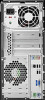
6. Remove the two retainer screws that secure the drive to the bay (1) then slide the drive forward and out of the bay (2). Figure 8-9 Removing a 5.25-inch External Drive Installing an Optical Drive into the 5.25-inch Drive Bay To install an optional 5.25-inch optical drive: 1. Prepare the computer for disassembly (Preparation for Disassembly on page 83). 2. Remove the access panel (Access Panel on page 84). 3. Remove the front bezel (Front Bezel on page 85). 4. If you are installing a drive in a bay covered by a bezel blank, remove the front bezel then remove the bezel blank. 5. Install the guide screw in the front top hole on the left side of the drive. Figure 8-10 Installing the Guide Screw in the Optical Drive Drives 93
-
 1
1 -
2
-
3
-
4
-
5
-
6
-
7
-
8
-
9
-
10
-
11
-
12
-
13
-
14
-
15
-
16
-
17
-
18
-
19
-
20
-
21
-
22
-
23
-
24
-
25
-
26
-
27
-
28
-
29
-
30
-
31
-
32
-
33
-
34
-
35
-
36
-
37
-
38
-
39
-
40
-
41
-
42
-
43
-
44
-
45
-
46
-
47
-
48
-
49
-
50
-
51
-
52
-
53
-
54
-
55
-
56
-
57
-
58
-
59
-
60
-
61
-
62
-
63
-
64
-
65
-
66
-
67
-
68
-
69
-
70
-
71
-
72
-
73
-
74
-
75
-
76
-
77
-
78
-
79
-
80
-
81
-
82
-
83
-
84
-
85
-
86
-
87
-
88
-
89
-
90
-
91
-
92
-
93
-
94
-
95
-
96
-
97
-
 98
98 -
 99
99 -
 100
100 -
 101
101 -
 102
102 -
 103
103 -
 104
104 -
 105
105 -
 106
106 -
 107
107 -
 108
108 -
109
-
110
-
111
-
112
-
113
-
114
-
115
-
116
-
117
-
118
-
119
-
120
-
121
-
122
-
123
-
124
-
125
-
126
-
127
-
128
-
129
-
130
-
131
-
132
-
133
-
134
-
135
-
136
-
137
-
138
-
139
-
140
-
141
-
142
-
143
-
144
-
145
-
146
-
147
-
148
-
149
-
150
-
151
-
152
-
153
-
154
-
155
-
156
-
157
-
158
-
159
-
160
-
161
-
162
 |
 |

6.
Remove the two retainer screws that secure the drive to the bay
(1)
then slide the drive forward
and out of the bay
(2)
.
Figure 8-9
Removing a 5.25-inch External Drive
Installing an Optical Drive into the 5.25-inch Drive Bay
To install an optional 5.25-inch optical drive:
1.
Prepare the computer for disassembly (
Preparation for Disassembly
on page
83
).
2.
Remove the access panel (
Access Panel
on page
84
).
3.
Remove the front bezel (
Front Bezel
on page
85
).
4.
If you are installing a drive in a bay covered by a bezel blank, remove the front bezel then remove
the bezel blank.
5.
Install the guide screw in the front top hole on the left side of the drive.
Figure 8-10
Installing the Guide Screw in the Optical Drive
Drives
93