Compaq dx2810 Service Reference Guide: HP Compaq dx2810 and dx2818 Business PC - Page 124
Front I/O Device
 |
View all Compaq dx2810 manuals
Add to My Manuals
Save this manual to your list of manuals |
Page 124 highlights
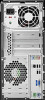
Front I/O Device 1. Prepare the computer for disassembly (Preparation for Disassembly on page 83). 2. Remove the access panel (Access Panel on page 84). 3. Remove the front bezel (Front Bezel on page 85). 4. Rotate the drive cage to its upright position. 5. Unplug the audio cable from the yellow system board connector labeled F_AUDIO. 6. Unplug the USB cable from the white system board connector labeled F_USB1. 7. Rotate the drive cage back down. 8. Remove the screw that secures the front I/O device to the chassis (1). 9. Rotate the assembly toward the right side of the chassis (2), and then slide the device slightly toward the left (3) to disengage the tab on the right side of the assembly from the chassis. Thread the wires through the hole in the chassis and remove the assembly. NOTE: If necessary, rotate the drive cage back up to better access the hole you thread the cables through. To install the front I/O device, reverse the removal procedures. 114 Chapter 8 Removal and Replacement Procedures Small Form Factor (SFF) Chassis
-
 1
1 -
2
-
3
-
4
-
5
-
6
-
7
-
8
-
9
-
10
-
11
-
12
-
13
-
14
-
15
-
16
-
17
-
18
-
19
-
20
-
21
-
22
-
23
-
24
-
25
-
26
-
27
-
28
-
29
-
30
-
31
-
32
-
33
-
34
-
35
-
36
-
37
-
38
-
39
-
40
-
41
-
42
-
43
-
44
-
45
-
46
-
47
-
48
-
49
-
50
-
51
-
52
-
53
-
54
-
55
-
56
-
57
-
58
-
59
-
60
-
61
-
62
-
63
-
64
-
65
-
66
-
67
-
68
-
69
-
70
-
71
-
72
-
73
-
74
-
75
-
76
-
77
-
78
-
79
-
80
-
81
-
82
-
83
-
84
-
85
-
86
-
87
-
88
-
89
-
90
-
91
-
92
-
93
-
94
-
95
-
96
-
97
-
98
-
99
-
100
-
101
-
102
-
103
-
104
-
105
-
106
-
107
-
108
-
109
-
110
-
111
-
112
-
113
-
114
-
115
-
116
-
117
-
118
-
 119
119 -
 120
120 -
 121
121 -
 122
122 -
 123
123 -
 124
124 -
 125
125 -
 126
126 -
 127
127 -
 128
128 -
 129
129 -
130
-
131
-
132
-
133
-
134
-
135
-
136
-
137
-
138
-
139
-
140
-
141
-
142
-
143
-
144
-
145
-
146
-
147
-
148
-
149
-
150
-
151
-
152
-
153
-
154
-
155
-
156
-
157
-
158
-
159
-
160
-
161
-
162
 |
 |
