Compaq dx2810 Service Reference Guide: HP Compaq dx2810 and dx2818 Business PC - Page 131
Removing or Installing an Expansion Card, Front Bezel
 |
View all Compaq dx2810 manuals
Add to My Manuals
Save this manual to your list of manuals |
Page 131 highlights
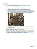
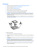
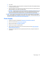
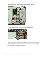
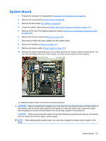
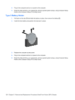
System Board 1. Prepare the computer for disassembly (Preparation for Disassembly on page 83). 2. Remove the access panel (Access Panel on page 84). 3. Remove the front bezel (Front Bezel on page 85). 4. Loosen the plastic cable fasteners (Plastic Wire/Cable Fastener and Clips on page 113). 5. Remove all PCI and PCI Express expansion boards (Removing or Installing an Expansion Card on page 109). 6. Remove all memory modules (Memory on page 104). 7. Disconnect all data and power cables from the system board. 8. Remove the heatsink (Heatsink on page 117). 9. Remove the power supply (Power Supply on page 119). 10. Remove the eight screws that secure the system board to the chassis, slide the board about 1.25 cm (1/2 inch) toward the front of the chassis, and then lift the board out of the chassis. To install the system board, reverse the removal procedure. CAUTION: Before reinstalling the heatsink you must clean the top of the processor and the bottom of the heatsink with an alcohol pad supplied in the spares kit. After the alcohol has evaporated, apply thermal grease to the top of the processor from the syringe supplied in the spares kit. CAUTION: When reconnecting the cables it is important that they be positioned so they do not interfere with the rotation of the drive cage or power supply. NOTE: When replacing the system board, you must also change the chassis serial number in the BIOS. System Board 121
-
 1
1 -
2
-
3
-
4
-
5
-
6
-
7
-
8
-
9
-
10
-
11
-
12
-
13
-
14
-
15
-
16
-
17
-
18
-
19
-
20
-
21
-
22
-
23
-
24
-
25
-
26
-
27
-
28
-
29
-
30
-
31
-
32
-
33
-
34
-
35
-
36
-
37
-
38
-
39
-
40
-
41
-
42
-
43
-
44
-
45
-
46
-
47
-
48
-
49
-
50
-
51
-
52
-
53
-
54
-
55
-
56
-
57
-
58
-
59
-
60
-
61
-
62
-
63
-
64
-
65
-
66
-
67
-
68
-
69
-
70
-
71
-
72
-
73
-
74
-
75
-
76
-
77
-
78
-
79
-
80
-
81
-
82
-
83
-
84
-
85
-
86
-
87
-
88
-
89
-
90
-
91
-
92
-
93
-
94
-
95
-
96
-
97
-
98
-
99
-
100
-
101
-
102
-
103
-
104
-
105
-
106
-
107
-
108
-
109
-
110
-
111
-
112
-
113
-
114
-
115
-
116
-
117
-
118
-
119
-
120
-
121
-
122
-
123
-
124
-
125
-
 126
126 -
 127
127 -
 128
128 -
 129
129 -
 130
130 -
 131
131 -
 132
132 -
 133
133 -
 134
134 -
 135
135 -
 136
136 -
137
-
138
-
139
-
140
-
141
-
142
-
143
-
144
-
145
-
146
-
147
-
148
-
149
-
150
-
151
-
152
-
153
-
154
-
155
-
156
-
157
-
158
-
159
-
160
-
161
-
162
 |
 |
