Compaq dx2810 Service Reference Guide: HP Compaq dx2810 and dx2818 Business PC - Page 125
Power Switch Assembly, on the top of assembly from the chassis.
 |
View all Compaq dx2810 manuals
Add to My Manuals
Save this manual to your list of manuals |
Page 125 highlights
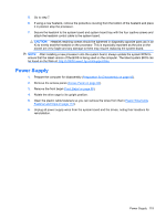
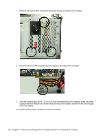
Power Switch Assembly 1. Prepare the computer for disassembly (Preparation for Disassembly on page 83). 2. Remove the access panel (Access Panel on page 84). 3. Remove the front bezel (Front Bezel on page 85). 4. Rotate the drive cage to its upright position. 5. Disconnect the power switch wires from the black system board connector labeled F_PANEL. 6. Rotate the drive cage back down. 7. Press the tab on the bottom of the assembly to disengage it from the chassis (1). 8. Slide the assembly downward to disengage the tab (2) on the top of assembly from the chassis. 9. If necessary, rotate the drive cage back up to gain access to the wires. 10. Pull the assembly out through front of unit (3) while threading the wires through the hole in the chassis. To install the power switch assembly, reverse the removal procedure. Power Switch Assembly 115
-
 1
1 -
2
-
3
-
4
-
5
-
6
-
7
-
8
-
9
-
10
-
11
-
12
-
13
-
14
-
15
-
16
-
17
-
18
-
19
-
20
-
21
-
22
-
23
-
24
-
25
-
26
-
27
-
28
-
29
-
30
-
31
-
32
-
33
-
34
-
35
-
36
-
37
-
38
-
39
-
40
-
41
-
42
-
43
-
44
-
45
-
46
-
47
-
48
-
49
-
50
-
51
-
52
-
53
-
54
-
55
-
56
-
57
-
58
-
59
-
60
-
61
-
62
-
63
-
64
-
65
-
66
-
67
-
68
-
69
-
70
-
71
-
72
-
73
-
74
-
75
-
76
-
77
-
78
-
79
-
80
-
81
-
82
-
83
-
84
-
85
-
86
-
87
-
88
-
89
-
90
-
91
-
92
-
93
-
94
-
95
-
96
-
97
-
98
-
99
-
100
-
101
-
102
-
103
-
104
-
105
-
106
-
107
-
108
-
109
-
110
-
111
-
112
-
113
-
114
-
115
-
116
-
117
-
118
-
119
-
 120
120 -
 121
121 -
 122
122 -
 123
123 -
 124
124 -
 125
125 -
 126
126 -
 127
127 -
 128
128 -
 129
129 -
 130
130 -
131
-
132
-
133
-
134
-
135
-
136
-
137
-
138
-
139
-
140
-
141
-
142
-
143
-
144
-
145
-
146
-
147
-
148
-
149
-
150
-
151
-
152
-
153
-
154
-
155
-
156
-
157
-
158
-
159
-
160
-
161
-
162
 |
 |
