Compaq dx7500 Service Reference Guide: HP Compaq dx7500 Business PC
Compaq dx7500 - Microtower PC Manual
 |
View all Compaq dx7500 manuals
Add to My Manuals
Save this manual to your list of manuals |
Compaq dx7500 manual content summary:
- Compaq dx7500 | Service Reference Guide: HP Compaq dx7500 Business PC - Page 1
Service Reference Guide HP Compaq dx7500 Business PC - Compaq dx7500 | Service Reference Guide: HP Compaq dx7500 Business PC - Page 2
and Windows are trademarks of Microsoft Corporation in the U.S. and other countries. The only warranties for HP products and services are without the prior written consent of Hewlett-Packard Company. Service Reference Guide Business PCs Second Edition (December 2008) First Edition (September 2008) - Compaq dx7500 | Service Reference Guide: HP Compaq dx7500 Business PC - Page 3
About This Book WARNING! Text set off in this manner indicates that failure to follow directions could result in bodily harm or loss of life. CAUTION: Text set off in this manner indicates that failure to follow directions could result in damage to equipment or loss of information. NOTE: Text set - Compaq dx7500 | Service Reference Guide: HP Compaq dx7500 Business PC - Page 4
iv About This Book - Compaq dx7500 | Service Reference Guide: HP Compaq dx7500 Business PC - Page 5
14 4 Desktop Management Initial Configuration and Deployment 15 HP Software Agent ...16 Altiris Deployment Solution Agent 16 Remote System Installation ...17 Software Updating and Management 17 HP Client Management Interface 17 HP SoftPaq Download Manager 18 HP System Software Manager 18 HP - Compaq dx7500 | Service Reference Guide: HP Compaq dx7500 Business PC - Page 6
Supported USB Flash Media Device 26 Unsupported USB Flash Media Device 27 Dual-State Power Button ...29 HP Web Site Support Protection System ...34 Surge-Tolerant Power Supply 34 Thermal Sensor ...34 5 Designations ...37 Microtower (MT) ...37 Small Form Factor (SFF 38 Electrostatic Discharge - Compaq dx7500 | Service Reference Guide: HP Compaq dx7500 Business PC - Page 7
...43 Cleaning the Mouse ...43 Service Considerations ...43 Power Supply Fan ...43 Tools and Software Requirements 43 Screws ...44 Cables and Connectors ...44 Hard Drives ...44 Lithium Coin Cell Battery 44 7 Removal and Replacement Procedures Microtower (MT) Chassis Serial Number Location ...46 - Compaq dx7500 | Service Reference Guide: HP Compaq dx7500 Business PC - Page 8
...86 Type 3 Battery Holder ...87 Installing a Security Lock ...88 Cable Lock ...88 Padlock ...88 HP Business PC Security Lock 89 8 Removal and Replacement Procedures Small Form Factor (SFF) Chassis Preparation for Disassembly ...91 Access Panel ...92 Front Bezel ...93 Bezel Blanks ...94 Cable - Compaq dx7500 | Service Reference Guide: HP Compaq dx7500 Business PC - Page 9
Problems 176 Solving Internet Access Problems ...177 Solving Software Problems ...179 Interpreting POST Audible Codes ...180 Resetting the Password Jumper ...181 Resetting the CMOS Jumper ...182 Contacting Customer Support ...183 Appendix D Specifications Minitower ...184 Small Form Factor - Compaq dx7500 | Service Reference Guide: HP Compaq dx7500 Business PC - Page 10
Index ...186 x - Compaq dx7500 | Service Reference Guide: HP Compaq dx7500 Business PC - Page 11
action points the operating system to the appropriate drivers. Obtain the latest support software, including support software for the operating system from http://www.hp.com/support. Select your country and language, select Download drivers and software (and firmware), enter the model number of the - Compaq dx7500 | Service Reference Guide: HP Compaq dx7500 Business PC - Page 12
CD or DVD discs, while all backups can be copied to network or secondary hard disks. HP highly HP Backup and Recovery Manager User Guide by selecting Start > HP Backup and Recovery > HP Backup and Recovery Manager Manual. NOTE: You can order a Recovery Disc Set from HP by calling the HP support - Compaq dx7500 | Service Reference Guide: HP Compaq dx7500 Business PC - Page 13
: ● Change factory default settings. ● Set the system date and time. ● Set, view, change, or verify the system configuration, including settings for graphics, audio, storage, communications, and input devices. ● View settings for processor and memory. ● Modify the boot order of bootable devices such - Compaq dx7500 | Service Reference Guide: HP Compaq dx7500 Business PC - Page 14
◦ Transfer Mode ● Smart Support - run HDD self-test for selected channel: ◦ SMART Status Check ◦ SMART Short Self-Test ◦ SMART Extended Self-Test System Information (view only) ● Installed Memory ● Memory Bank 1 ● Memory Bank 2 ● Memory Bank 3 ● Memory Bank 4 ● BIOS Revision ● Core Version ● Model - Compaq dx7500 | Service Reference Guide: HP Compaq dx7500 Business PC - Page 15
onboard LAN controller. Onboard LAN Boot ROM Allows you to disable/enable the boot ROM of the onboard LAN chip. SATA1 Controller Allows you to disable/enable the SATA1 Controller. SATA1 Controller Mode If SATA1 Controller is enabled, allows you to set the mode to: ● IDE ● AHCI ● RAID Computer - Compaq dx7500 | Service Reference Guide: HP Compaq dx7500 Business PC - Page 16
Allows you to change the supervisor password. Computer Setup-Power NOTE: Support for specific Computer Setup options may vary depending on the hardware configuration. Table 2-3 Computer Setup-Power Option Description After AC Power Failure Allows you to select system restart behavior after - Compaq dx7500 | Service Reference Guide: HP Compaq dx7500 Business PC - Page 17
device priority within CD/DVD drives. Priority Hard Drive Group Boot Specifies boot device priority within hard drives. Priority Network Group Boot Priority Specifies boot device priority within bootable network devices. Computer Setup-Exit NOTE: Support for specific Computer Setup options may - Compaq dx7500 | Service Reference Guide: HP Compaq dx7500 Business PC - Page 18
Recovering the Configuration Settings To reset all BIOS Setup options to their default values (including options for ctrl+F10), you must enter F10 Setup mode and press F5. This does not include updates to system date, system time, supervisor password, user password, and CPU frequency multiplier. 8 - Compaq dx7500 | Service Reference Guide: HP Compaq dx7500 Business PC - Page 19
Select Create a set of recovery discs (Recommended) and click Next. 3. Follow the instructions in the wizard to create a Recovery Disc Set. 4. Use Windows Explorer to search the Recovery Disc Set for the CD with the compaq\hpdiags directory. 5. While the computer is on, insert the CD into an optical - Compaq dx7500 | Service Reference Guide: HP Compaq dx7500 Business PC - Page 20
in the computer. This includes memory slots on the system board and any memory modules installed. Miscellaneous-Shows HP Insight Diagnostics version information, computer configuration memory (CMOS) information, system board data, and system management BIOS data. Storage-Shows information about - Compaq dx7500 | Service Reference Guide: HP Compaq dx7500 Business PC - Page 21
The Custom Test mode allows you to specifically select which devices, tests, and test parameters are run. For each test type, there are two test modes to choose from: ● Interactive Mode-Provides maximum control over the testing process. The diagnostic software will prompt you for input during tests - Compaq dx7500 | Service Reference Guide: HP Compaq dx7500 Business PC - Page 22
The Help tab contains an HP Insight Diagnostics tab, an Error Codes tab, and a Test Components tab. The HP Insight Diagnostics tab contains corresponding error Message and a Recommended Repair action that should help solve the problem. To find an error code description quickly, enter the code in the - Compaq dx7500 | Service Reference Guide: HP Compaq dx7500 Business PC - Page 23
Insight Diagnostics 1. Go to http://www.hp.com. 2. Click the Support & Drivers link. 3. Select Download drivers and software (and firmware). 4. Enter your product number (for example, dx7500) in the text box and press the Enter key. 5. Select your specific computer model. 6. Select your OS. 7. Click - Compaq dx7500 | Service Reference Guide: HP Compaq dx7500 Business PC - Page 24
CD or DVD discs, while all backups can be copied to network or secondary hard disks. HP highly HP Backup and Recovery Manager User Guide by selecting Start > HP Backup and Recovery > HP Backup and Recovery Manager Manual. NOTE: You can order a Recovery Disc Set from HP by calling the HP support - Compaq dx7500 | Service Reference Guide: HP Compaq dx7500 Business PC - Page 25
of desktop management are: ● Initial configuration and deployment ● Remote system installation ● Software updating and management ● ROM flash ● Hardware option configuration ● Asset tracking and security ● Fault notification and recovery NOTE: Support for specific features described in this guide - Compaq dx7500 | Service Reference Guide: HP Compaq dx7500 Business PC - Page 26
. To install Altiris Deployment Solution Agent: 1. Click Start. 2. Click All Programs. 3. For Windows Vista, click Install Altiris DAgent. For Windows XP, click Install Altiris AClient. 4. Follow the onscreen instructions to set up and configure the Altiris client. This agent is a key infrastructure - Compaq dx7500 | Service Reference Guide: HP Compaq dx7500 Business PC - Page 27
● Formatting a hard drive ● Deploying a software image on one or more new PCs ● Remotely updating the system BIOS in flash ROM (Remote ROM Flash on page 23) ● Configuring the system BIOS settings To initiate Remote System Installation, press F12 when the F12 = Network Service Boot message appears in - Compaq dx7500 | Service Reference Guide: HP Compaq dx7500 Business PC - Page 28
the softpaqs you need. To download HP SoftPaq Download Manager, visit http://www.hp.com/go/sdm. HP System Software Manager HP System Software Manager (SSM) is a free utility that automates remote deployment of device drivers and BIOS updates for your networked HP business PCs. When SSM runs, it - Compaq dx7500 | Service Reference Guide: HP Compaq dx7500 Business PC - Page 29
free product for managing HP desktops, notebooks and workstations, providing hardware and software inventory, remote control, HP alert monitoring, HP BIOS and driver updates, and integration with HP Protect Tools. The Starter Edition also supports deployment and management of HP Thin Clients. ● The - Compaq dx7500 | Service Reference Guide: HP Compaq dx7500 Business PC - Page 30
drivers and BIOS updates without visiting each PC ● Remotely configure BIOS and security settings ● Automate processes to quickly resolve hardware problems Tight integration with HP Instant Support tools reduces hardware troubleshooting time. ● Diagnostics-remotely run & view reports on HP desktop - Compaq dx7500 | Service Reference Guide: HP Compaq dx7500 Business PC - Page 31
information on HP business desktops, notebooks and workstations. It can be used in conjunction with the custom inventory and update features of Microsoft products to provide automated driver and patch updates to managed HP client computers. Microsoft products supported by the HP Client Catalog - Compaq dx7500 | Service Reference Guide: HP Compaq dx7500 Business PC - Page 32
each PC consumes. It also provides control over PC power settings enabling administrators to easily implement energy saving strategies across their networks. An HP SoftPaq containing the Surveyor agent may be downloaded from the HP Support site and installed on supported commercial desktop models - Compaq dx7500 | Service Reference Guide: HP Compaq dx7500 Business PC - Page 33
ROM from being unintentionally updated or overwritten. This is important to ensure the operating integrity of the computer. Should you need or want to upgrade the BIOS, you may download the latest BIOS images from the HP driver and support page, http://www.hp.com/support/files. CAUTION: For maximum - Compaq dx7500 | Service Reference Guide: HP Compaq dx7500 Business PC - Page 34
successfully reprograms the ROM, the system will automatically power off. 4. Remove the removable media used to upgrade the BIOS. 5. Turn the power on to restart the computer. NOTE: BitLocker prevents Windows Vista from booting when a CD containing the BIOS image file is in an optical drive. If - Compaq dx7500 | Service Reference Guide: HP Compaq dx7500 Business PC - Page 35
instructions on specific Windows XP is not available to use to create a bootable diskette, use the method for copying to a single computer instead (see Copying to Single Computer on page 24). 1. Create a bootable diskette or USB flash media device. See Supported Windows, click Start > Shut Down > Shut - Compaq dx7500 | Service Reference Guide: HP Compaq dx7500 Business PC - Page 36
the configuration diskette or USB flash media device. 8. Download a BIOS utility for replicating setup (repset.exe) and copy it onto the configuration diskette or USB flash media device. To obtain this utility, go to http://welcome.hp.com/country/us/en/ support.html and enter the model number of the - Compaq dx7500 | Service Reference Guide: HP Compaq dx7500 Business PC - Page 37
4. If none are found, either the system does not support the USB flash media device or the USB flash media device If you have used a DOS version from Windows 9x, you may see a brief Windows logo screen. If you do not want this PC that is bootable from a USB flash media device Replicating the Setup 27 - Compaq dx7500 | Service Reference Guide: HP Compaq dx7500 Business PC - Page 38
any PCI cards in the system that have SCSI, ATA RAID or SATA drives attached, turn off the computer and unplug the power cord. CAUTION: The power cord MUST PCI Devices and re-enable the PATA and SATA controllers that were disabled in step 6. Put the SATA controller on its original IRQ. 16. Save the - Compaq dx7500 | Service Reference Guide: HP Compaq dx7500 Business PC - Page 39
installing the latest support software easier. You can download the software from http://www.hp.com/support. The Web site contains the latest device drivers, utilities, and flashable ROM images needed to run the latest Microsoft Windows operating system on the HP computer. Dual-State Power Button 29 - Compaq dx7500 | Service Reference Guide: HP Compaq dx7500 Business PC - Page 40
. See the Computer Setup (F10) Utility Guide included with the computer for additional information and instructions on using the Computer Setup Utilities. Some computers also have HP BIOS Configuration for ProtectTools, which is a Windows-based component of ProtectTools that allows administrators to - Compaq dx7500 | Service Reference Guide: HP Compaq dx7500 Business PC - Page 41
plug and play settings under Windows. Network Service Boot Enables/disables the computer's ability to boot from an operating system installed on a network server. (Feature available on NIC models only; the network controller must be either a PCI expansion card or embedded on the system board - Compaq dx7500 | Service Reference Guide: HP Compaq dx7500 Business PC - Page 42
an embedded security device, refer to the HP ProtectTools Security Manager Guide at http://www.hp.com. 1. Turn on or restart the computer. If you are in Windows, click Start > Shut Down > Restart the Computer. 2. To modify the password, and then type the new password. 32 Chapter 4 Desktop Management - Compaq dx7500 | Service Reference Guide: HP Compaq dx7500 Business PC - Page 43
HP ProtectTools Security Manager Guide at http://www.hp.com. 1. Turn on or restart the computer. If you are in Windows, click Start > Shut Each keyboard is designed to meet country-specific requirements. The syntax and keys that you the Troubleshooting Guide for instructions on clearing passwords. Asset - Compaq dx7500 | Service Reference Guide: HP Compaq dx7500 Business PC - Page 44
the hard drive. The service provider can use this information to help diagnose conditions that caused you to run the DPS software. Refer to the Troubleshooting Guide for instructions on using DPS. Surge-Tolerant Power Supply An integrated surge-tolerant power supply provides greater reliability when - Compaq dx7500 | Service Reference Guide: HP Compaq dx7500 Business PC - Page 45
Drive Guidelines and Features NOTE: HP only supports the use of SATA hard drives on these models of computer. No Parallel ATA (PATA) drives are supported. SATA Hard Drives Serial ATA Hard Drive Characteristics Number of pins/conductors in data cable Number of pins in power cable Maximum data cable - Compaq dx7500 | Service Reference Guide: HP Compaq dx7500 Business PC - Page 46
computer specification. Drive size calculations by drive manufacturers are bytes to the base 10 while calculations by Microsoft are bytes to the base 2. File System FAT 32 NTFS Drive/Partition Capacity Limits Controller Type ATA ATA Operating System Windows 2000/XP/Vista Windows 2000/XP/Vista - Compaq dx7500 | Service Reference Guide: HP Compaq dx7500 Business PC - Page 47
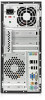
to the system board. You must disconnect the power cord from the power source before opening the computer to prevent system board or component damage. Chassis Designations The following subsection illustrates the dx7500 chassis design. Microtower (MT) NOTE: The appearance of the front bezel may - Compaq dx7500 | Service Reference Guide: HP Compaq dx7500 Business PC - Page 48
Small Form Factor (SFF) NOTE: The appearance of the front bezel may vary. Electrostatic Discharge layers, reducing its life expectancy. Networks built into many integrated circuits provide some protection, but in many cases, the discharge contains enough power to alter device parameters or melt - Compaq dx7500 | Service Reference Guide: HP Compaq dx7500 Business PC - Page 49
Removing bubble pack from PCB 7,000 V Packing PCBs in foam-lined box 5,000 V *These are then multi-packaged inside plastic tubes, trays, or Styrofoam. 20,000 V 11,000 V 26,500 V 21,000 V NOTE: 700 volts can degrade a product. Preventing Electrostatic Damage to Equipment Many electronic - Compaq dx7500 | Service Reference Guide: HP Compaq dx7500 Business PC - Page 50
. Handle them only at static-free work areas. ● Turn off power and input signals before inserting and removing connectors or test equipment. ● Static-dissipative table or floor mats with hard tie to ground ● Field service kits ● Static awareness labels ● Wrist straps and footwear straps providing one - Compaq dx7500 | Service Reference Guide: HP Compaq dx7500 Business PC - Page 51
the keyboard, with the keyboard feet down, directly against the front of the desktop unit as this also restricts airflow. ● Occasionally clean the air vents on all ● Install or enable power management functions of the operating system or other software, including sleep states. Operating Guidelines 41 - Compaq dx7500 | Service Reference Guide: HP Compaq dx7500 Business PC - Page 52
the keyboard body, follow the procedures described in Cleaning the Computer Case on page 42. When cleaning debris from under the keys, review all rules in General Cleaning Safety Precautions on page 42 before following these procedures: CAUTION: Use safety glasses equipped with side shields before - Compaq dx7500 | Service Reference Guide: HP Compaq dx7500 Business PC - Page 53
the power cord from the power source before opening the computer to prevent system board or component damage. Tools and Software Requirements To service the computer, you need the following: ● Torx T-15 screwdriver (HP screwdriver with bits, PN 161946-001) ● Torx T-15 screwdriver with small diameter - Compaq dx7500 | Service Reference Guide: HP Compaq dx7500 Business PC - Page 54
can damage the unit. HP strongly recommends that all . CAUTION: When servicing this computer, ensure power to the real-time clock and has a minimum lifetime of about three years. See the appropriate removal and replacement chapter for the chassis you are working on in this guide for instructions - Compaq dx7500 | Service Reference Guide: HP Compaq dx7500 Business PC - Page 55
with the general household waste. In order to forward them to recycling or proper disposal, please use the public collection system or return them to HP, their authorized partners, or their agents. Service Considerations 45 - Compaq dx7500 | Service Reference Guide: HP Compaq dx7500 Business PC - Page 56
7 Removal and Replacement Procedures Microtower (MT) Chassis Adherence to the procedures and precautions described in this chapter is essential for proper service. After completing all necessary removal and replacement procedures, run the Diagnostics utility to verify that all components operate - Compaq dx7500 | Service Reference Guide: HP Compaq dx7500 Business PC - Page 57
the cooling fan is on even when the computer is in the "Standby," or "Suspend" modes. The power cord should always be disconnected before servicing a unit. 5. Disconnect the power cord from the electrical outlet and then from the computer. 6. Disconnect all peripheral device cables from the computer - Compaq dx7500 | Service Reference Guide: HP Compaq dx7500 Business PC - Page 58
panel is facing up. Figure 7-2 Removing the Computer Access Panel To replace the access panel, reverse the removal steps. 48 Chapter 7 Removal and Replacement Procedures Microtower (MT) Chassis - Compaq dx7500 | Service Reference Guide: HP Compaq dx7500 Business PC - Page 59
Front Bezel 1. Prepare the computer for disassembly (Preparation for Disassembly on page 47). 2. Remove the access panel (Access Panel on page 48). 3. Press outward on the three latches on the right side of the bezel (1), then rotate the right side of the bezel off the chassis (2) followed by the - Compaq dx7500 | Service Reference Guide: HP Compaq dx7500 Business PC - Page 60
blanks covering the 3.5-inch and 5.25-inch external drive bays that need to be removed before installing a drive. To remove a bezel blank: 1. Follow the instructions described in Front Bezel on page 49. 2. Press the two retaining tabs towards the outer left edge of the bezel (1) and pull the bezel - Compaq dx7500 | Service Reference Guide: HP Compaq dx7500 Business PC - Page 61
) and CAS latency 6 DDR2 800 Mhz (6-6-6 timing) ● contain the mandatory JEDEC SPD information In addition, the computer supports: ● 512Mbit, 1Gbit, and 2Gbit non-ECC memory technologies ● single-sided and double-sided DIMMs ● DIMMs constructed with x8 and x16 DDR devices; DIMMs constructed with x4 - Compaq dx7500 | Service Reference Guide: HP Compaq dx7500 Business PC - Page 62
DIMM2 operate in memory channel A. Sockets DIMM3 and DIMM4 operate in memory channel B. mode if the total memory capacity of the DIMMs in Channel A is equal to the total memory capacity of the if the total memory capacity of the DIMMs in Channel A is not equal to the total memory capacity of the - Compaq dx7500 | Service Reference Guide: HP Compaq dx7500 Business PC - Page 63
always supplied to the memory modules as long as the computer is plugged into an active AC outlet. Adding or removing memory modules while voltage is present may cause irreparable damage to the memory modules or system board. The memory module sockets have gold-plated metal contacts. When upgrading - Compaq dx7500 | Service Reference Guide: HP Compaq dx7500 Business PC - Page 64
external devices, then turn on the computer. The computer should automatically recognize the additional memory when you turn on the computer. 9. Lock any security devices that were disengaged when the access panel was removed. 54 Chapter 7 Removal and Replacement Procedures Microtower (MT) Chassis - Compaq dx7500 | Service Reference Guide: HP Compaq dx7500 Business PC - Page 65
x1 expansion slots and one PCI Express x16 expansion slot. The expansion slots accommodate full-height or half-height expansion cards. Figure 7-7 Expansion Slot Locations Table 7-2 Expansion Slot Locations Item Description 1 PCI Express x1 expansion slot 2 PCI Express x1 expansion slot - Compaq dx7500 | Service Reference Guide: HP Compaq dx7500 Business PC - Page 66
to pry out the metal shield on the rear panel that covers the expansion slot. Be sure to remove the appropriate shield for the expansion card you are installing. Figure 7-9 Removing an Expansion Slot Cover 56 Chapter 7 Removal and Replacement Procedures Microtower (MT) Chassis - Compaq dx7500 | Service Reference Guide: HP Compaq dx7500 Business PC - Page 67
it back and forth until the connectors pull free from the socket. Be sure not to scrape the card against the other components. Figure 7-10 Removing a PCI Express x1 Expansion Card c. If you are removing a PCI Express x16 card, pull the retention arm on the back of the expansion socket away from the - Compaq dx7500 | Service Reference Guide: HP Compaq dx7500 Business PC - Page 68
on the card so that the whole connector seats properly in the expansion card slot. 9. Replace the slot cover lock and secure it in place with the screw that was previously removed. Figure 7-13 Securing the Expansion Cards and Slot Covers 58 Chapter 7 Removal and Replacement Procedures Microtower (MT - Compaq dx7500 | Service Reference Guide: HP Compaq dx7500 Business PC - Page 69
Guide for instructions on using Computer Setup. Cable Management Always follow good cable management practices when working inside the computer. ● Keep cables away from major heat sources like the heatsink. ● Do not jam cables on top of expansion cards or memory modules. Printed circuit cards - Compaq dx7500 | Service Reference Guide: HP Compaq dx7500 Business PC - Page 70
2. Grasp the cable end of the connector and pull it straight up (2). CAUTION: Always pull the connector - NEVER pull on the cable. Pulling on the cable could damage the cable and result in a failed power supply. 60 Chapter 7 Removal and Replacement Procedures Microtower (MT) Chassis - Compaq dx7500 | Service Reference Guide: HP Compaq dx7500 Business PC - Page 71
White Red Black dark blue white red black Description Power supply, 24-pin Power supply, 4-pin Diskette drive Chassis fan Heatsink fan Front power button/LED Front I/O USB cable Front I/O audio Internal speaker Serial port Media card reader Primary hard drive Primary optical drive Second hard - Compaq dx7500 | Service Reference Guide: HP Compaq dx7500 Business PC - Page 72
supports up to five drives that may be installed in various configurations. This section describes the procedure for replacing or upgrading the storage drives. A Torx T-15 screwdriver is needed to remove and install the guide drive bay for optional drive (media card reader shown) 3 Primary 3.5-inch - Compaq dx7500 | Service Reference Guide: HP Compaq dx7500 Business PC - Page 73
labeled FLOPPY. ● Connect a media card reader to the USB connector labeled F_USB2. ● The system does not support Parallel ATA (PATA) optical drives or other drives use M3 metric screws. The HP-supplied M3 metric guide screws (1) are black. The HP-supplied 6-32 standard screws (2) are silver. Figure - Compaq dx7500 | Service Reference Guide: HP Compaq dx7500 Business PC - Page 74
: If you are inserting or removing a drive, shut down the operating system properly, turn off the computer, and unplug the power cord. Do not remove a drive while the computer No. System Board Connector System Board Label 1 Media Card Reader F_USB2 2 SATA4 SATA4 3 SATA5 SATA5 4 SATA1 - Compaq dx7500 | Service Reference Guide: HP Compaq dx7500 Business PC - Page 75
for Disassembly on page 47). 2. Remove the access panel (Access Panel on page 48). 3. Remove the front bezel (Front Bezel on page 49). 4. Disconnect the power cable (1) and data cable (2) from the rear of the optical drive. Figure 7-17 Disconnecting the - Compaq dx7500 | Service Reference Guide: HP Compaq dx7500 Business PC - Page 76
has screws installed on the sides of the drive, remove the screws before inserting the drive into the chassis. 66 Chapter 7 Removal and Replacement Procedures Microtower (MT) Chassis - Compaq dx7500 | Service Reference Guide: HP Compaq dx7500 Business PC - Page 77
cable (1) and data cable (2) to the rear of the optical drive. Figure 7-20 Connecting the Power and Data Cables 10. Replace the front bezel and access panel. 11. Reconnect the power cord and turn on the computer. 12. Lock any security devices that were disengaged when the access panel was removed - Compaq dx7500 | Service Reference Guide: HP Compaq dx7500 Business PC - Page 78
NOTE: The 3.5-inch drive bay may contain a diskette drive or a media card reader. 1. Prepare the computer for disassembly (Preparation for Disassembly on page 47). are removing a diskette drive, disconnect the data cable (1) and power cable (2) from the back of the drive. Figure 7-21 Disconnecting - Compaq dx7500 | Service Reference Guide: HP Compaq dx7500 Business PC - Page 79
screws that secure the drive to the bay (1) then slide the drive forward and out of the bay (2). Figure 7-23 Removing a 3.5-inch Device (Media Card Reader Shown) NOTE: To install an external 3.5-inch drive, refer to Installing a Drive into the 3.5-inch External Drive Bay on page 70. Drives 69 - Compaq dx7500 | Service Reference Guide: HP Compaq dx7500 Business PC - Page 80
Card Reader Shown) 8. Connect the appropriate drive cables: a. If installing a diskette drive, connect the power and card reader, connect the USB cable from the media card reader to the USB connector on the system board labeled F_USB2. 70 Chapter 7 Removal and Replacement Procedures Microtower (MT - Compaq dx7500 | Service Reference Guide: HP Compaq dx7500 Business PC - Page 81
. 9. Replace the front bezel and access panel. 10. Reconnect the power cord and turn on the computer. 11. Lock any security devices that Recovery Disc Set to restore the operating system, software drivers, and any software applications that were preinstalled on the computer. If you do not have - Compaq dx7500 | Service Reference Guide: HP Compaq dx7500 Business PC - Page 82
the side of the hard drive cage (1), then slide the hard drive cage away from the bottom of the chassis (2) as shown below. Figure 7-26 Releasing the Hard Drive Cage 5. Lift the hard drive cage out of the chassis. Figure 7-27 Removing the Hard Drive Cage 72 Chapter 7 Removal and Replacement - Compaq dx7500 | Service Reference Guide: HP Compaq dx7500 Business PC - Page 83
6. Disconnect the power cable (1) and data cable (2) from the back of the hard drive. Figure 7-28 Disconnecting the Hard Drive Cables 7. Remove the four screws that secure the - Compaq dx7500 | Service Reference Guide: HP Compaq dx7500 Business PC - Page 84
63 for an illustration of the retainer screws location. Figure 7-30 Installing the Hard Drive in the Drive Cage 74 Chapter 7 Removal and Replacement Procedures Microtower (MT) Chassis - Compaq dx7500 | Service Reference Guide: HP Compaq dx7500 Business PC - Page 85
3. Connect the power cable (1) and data cable (2) to the back of the hard drive. Figure 7-31 Connecting the Hard Drive Cables CAUTION: Never crease or bend a SATA data - Compaq dx7500 | Service Reference Guide: HP Compaq dx7500 Business PC - Page 86
to avoid any hard drive performance problems. If you are adding a second computer access panel. 8. Reconnect the power cord and any external devices, software drivers, and any software applications that were preinstalled on the computer. 76 Chapter 7 Removal and Replacement Procedures Microtower (MT - Compaq dx7500 | Service Reference Guide: HP Compaq dx7500 Business PC - Page 87
Remove the screw (1) that secures the housing to the chassis, slide the housing up (2), and then pull the assembly away from the chassis while guiding the cables through the hole in the chassis. To install the housing assembly, reverse the removal procedures. Front I/O and USB Panel Housing Assembly - Compaq dx7500 | Service Reference Guide: HP Compaq dx7500 Business PC - Page 88
Power Switch/LED Assembly 1. Prepare the computer for disassembly (Preparation for the chassis while guiding the wires through the hole in the chassis. To install the power switch/LED assembly, reverse the removal procedures. 78 Chapter 7 Removal and Replacement Procedures Microtower (MT) Chassis - Compaq dx7500 | Service Reference Guide: HP Compaq dx7500 Business PC - Page 89
Speaker 1. Prepare the computer for disassembly (Preparation for Disassembly on page 47). 2. Remove the access panel (Access Panel on page 48). 3. Lay the computer on its side with the front facing toward you. 4. Remove the front bezel (Front Bezel on page 49). 5. Disconnect the speaker cable from - Compaq dx7500 | Service Reference Guide: HP Compaq dx7500 Business PC - Page 90
the fan forward, and then remove the fan from the chassis. To install the fan, reverse the removal procedures. 80 Chapter 7 Removal and Replacement Procedures Microtower (MT) Chassis - Compaq dx7500 | Service Reference Guide: HP Compaq dx7500 Business PC - Page 91
the access panel (Access Panel on page 48). 3. Lay the computer on its side with the rear facing toward you. 4. Disconnect the heatsink fan control cable from the system board. 5. Loosen the four captive screws that secure the heatsink to the system board. 6. Lift the heatsink from the processor - Compaq dx7500 | Service Reference Guide: HP Compaq dx7500 Business PC - Page 92
48). 3. Lay the computer on its side with the rear facing toward you. 4. Disconnect the heatsink control cable from the system board and remove the heatsink Heatsink assembly on page 81). 5. Rotate the locking atop the processor. 82 Chapter 7 Removal and Replacement Procedures Microtower (MT) Chassis - Compaq dx7500 | Service Reference Guide: HP Compaq dx7500 Business PC - Page 93
4 captive screws and attach the heatsink control cable to the system board. CAUTION: update the system ROM to ensure that the latest version of the BIOS is being used on the computer. The latest system ROM BIOS can be found on the Web at: http:///\h18000.www1.hp.com/support/files. Power Supply - Compaq dx7500 | Service Reference Guide: HP Compaq dx7500 Business PC - Page 94
Expansion Cards on page 55). 6. Disconnect the power, and data cables from the back of all installed drives. 7. Disconnect all cables from the system board. 8. Remove the eight screws that secure the system board to the chassis. 84 Chapter 7 Removal and Replacement Procedures Microtower (MT) Chassis - Compaq dx7500 | Service Reference Guide: HP Compaq dx7500 Business PC - Page 95
a new system board, always update the system ROM to ensure that the latest version of the BIOS is being used on the computer. The latest system ROM BIOS can be found at: http:///\h18000.www1.hp.com/support/files. Battery The battery that comes with your computer provides power to the real-time clock - Compaq dx7500 | Service Reference Guide: HP Compaq dx7500 Business PC - Page 96
panel. 5. Plug in the computer and turn on power to the computer. 6. Reset the date and time, your passwords, and any special system setups, using Computer Setup. Refer to the Computer Setup (F10) Utility Guide. Type 2 Battery Holder 1. To release the battery from its holder, squeeze the metal clamp - Compaq dx7500 | Service Reference Guide: HP Compaq dx7500 Business PC - Page 97
access panel. 4. Plug in the computer and turn on power to the computer. 5. Reset the date and time, your passwords, and any special system setups, using Computer Setup. Refer to the Computer Setup (F10) Utility Guide. Type 3 - Compaq dx7500 | Service Reference Guide: HP Compaq dx7500 Business PC - Page 98
4. Plug in the computer and turn on power to the computer. 5. Reset the date and time, your passwords, and any special system setups, using Computer Setup. Refer to the Computer Setup (F10) Utility Guide. Installing a Security Lock The security locks displayed below and on the following pages can be - Compaq dx7500 | Service Reference Guide: HP Compaq dx7500 Business PC - Page 99
HP Business PC Security Lock 1. Fasten the security cable by looping it around a stationary object. Figure 7-36 Securing the Cable to a Fixed Object 2. Thread the keyboard and mouse cables through the lock. Figure 7-37 Threading the Keyboard and Mouse Cables Installing a Security Lock 89 - Compaq dx7500 | Service Reference Guide: HP Compaq dx7500 Business PC - Page 100
button in (2) to engage the lock. Use the key provided to disengage the lock. Figure 7-39 Engaging the Lock 90 Chapter 7 Removal and Replacement Procedures Microtower (MT) Chassis - Compaq dx7500 | Service Reference Guide: HP Compaq dx7500 Business PC - Page 101
Small Form Factor (SFF) Chassis Adherence to the procedures and precautions described in this chapter is essential for proper service Not all features listed in this guide are available on all computers. Preparation for Disassembly 1. Close any open software applications. 2. Exit the operating system - Compaq dx7500 | Service Reference Guide: HP Compaq dx7500 Business PC - Page 102
(2). 4. Slide the access panel back about 1.3 cm (1/2 inch), then lift it away from and off the unit (3). Figure 8-1 Removing the Power Cord and Access Panel To install the access panel, reverse the removal procedure. 92 Chapter 8 Removal and Replacement Procedures Small Form Factor (SFF) Chassis - Compaq dx7500 | Service Reference Guide: HP Compaq dx7500 Business PC - Page 103
(Access Panel on page 92). 3. To remove the front bezel, pull up on each of the three tabs on the top of the bezel (1) to release them, then rotate the bezel down and off the chassis (2). Figure 8-2 Removing the Front Bezel To install the front bezel, reverse the removal procedure. Front - Compaq dx7500 | Service Reference Guide: HP Compaq dx7500 Business PC - Page 104
the outer edge of the bezel (1) and pull the bezel blank inwards to remove it (2). Figure 8-3 Removing a Bezel Blank 94 Chapter 8 Removal and Replacement Procedures Small Form Factor (SFF) Chassis - Compaq dx7500 | Service Reference Guide: HP Compaq dx7500 Business PC - Page 105
Cable Management The Small Form Factor chassis is a very compact computer and proper top of expansion cards or memory modules. Printed circuit cards like these are not designed to take excessive pressure on them. ● Keep cables clear of movable or rotating parts like the power supply and drive cage - Compaq dx7500 | Service Reference Guide: HP Compaq dx7500 Business PC - Page 106
Red White Black Description Front LED/Power cable Speaker cable Diskette drive Front audio cable Front I/O USB cable Primary hard drive data cable Optical drive data cable Heatsink fan cable Media card reader cable 96 Chapter 8 Removal and Replacement Procedures Small Form Factor (SFF) Chassis - Compaq dx7500 | Service Reference Guide: HP Compaq dx7500 Business PC - Page 107
screws on a drive. Drive Positions Figure 8-4 Drive Positions 1 3.5-inch external drive bay for optional drive (media card reader shown) 2 3.5-inch internal hard drive bay 3 5.25-inch external drive bay for optional drive (optical drive shown) To verify the type, size, and capacity - Compaq dx7500 | Service Reference Guide: HP Compaq dx7500 Business PC - Page 108
a media card reader to the USB connector labeled F_USB2. ● The system does not support Parallel ATA guide screws (1) are black. The HP-supplied 6-32 standard screws (2) are silver. Figure 8-5 Extra Drive Retainer Screws Location 98 Chapter 8 Removal and Replacement Procedures Small Form Factor (SFF - Compaq dx7500 | Service Reference Guide: HP Compaq dx7500 Business PC - Page 109
: To prevent loss of work and damage to the computer or drive: If you are inserting or removing a drive, shut down the operating system properly, turn off the computer, and unplug the power cord. Do not remove a drive while the computer is on or in standby mode. Before handling a drive, ensure that - Compaq dx7500 | Service Reference Guide: HP Compaq dx7500 Business PC - Page 110
No. System Board Connector System Board Label 1 Media Card Reader F_USB2 2 SATA4 SATA4 3 SATA5 SATA5 4 SATA1 SATA1 5 SATA0 SATA0 6 Diskette Drive FLOPPY Color black red black white dark blue black 100 Chapter 8 Removal and Replacement Procedures Small Form Factor (SFF) Chassis - Compaq dx7500 | Service Reference Guide: HP Compaq dx7500 Business PC - Page 111
(Access Panel on page 92). 3. Remove the front bezel (Front Bezel on page 93). 4. Disconnect the power cable (1) and data cable (2) from the rear of the optical drive. Figure 8-7 Disconnecting the Power and Data Cables 5. Rotate the drive cage all the way up. Figure 8-8 Rotating the Drive Cage Up - Compaq dx7500 | Service Reference Guide: HP Compaq dx7500 Business PC - Page 112
install an optical drive, refer to Installing an Optical Drive into the 5.25-inch Drive Bay on page 103. 102 Chapter 8 Removal and Replacement Procedures Small Form Factor (SFF) Chassis - Compaq dx7500 | Service Reference Guide: HP Compaq dx7500 Business PC - Page 113
in the Optical Drive 6. Rotate the drive cage all the way up. Figure 8-11 Rotating the Drive Cage Up 7. Align the guide screw on the drive with the slot on the chassis. Slide the optical drive into the drive bay until the two screw holes on the - Compaq dx7500 | Service Reference Guide: HP Compaq dx7500 Business PC - Page 114
8-13 Lowering the Drive Cage 10. Connect the SATA data cable to the red system board connector labeled SATA4. 104 Chapter 8 Removal and Replacement Procedures Small Form Factor (SFF) Chassis - Compaq dx7500 | Service Reference Guide: HP Compaq dx7500 Business PC - Page 115
. Figure 8-14 Connecting the Power and Data Cables 12. Replace the front bezel and access panel. 13. Reconnect the power cord and turn on the : The 3.5-inch drive bay may contain a diskette drive or a media card reader. 1. Prepare the computer for disassembly (Preparation for Disassembly on page 91 - Compaq dx7500 | Service Reference Guide: HP Compaq dx7500 Business PC - Page 116
back of the drive. Figure 8-15 Disconnecting the Diskette Drive Cables b. If you are removing a media card reader, disconnect the USB cable from the system board. Figure 8-16 Disconnecting the Media Card Reader Cable 106 Chapter 8 Removal and Replacement Procedures Small Form Factor (SFF) Chassis - Compaq dx7500 | Service Reference Guide: HP Compaq dx7500 Business PC - Page 117
retainer screws that secure the drive to the bay (1) then slide the drive forward and out of the bay (2). Figure 8-18 Removing a 3.5" Device (Media Card Reader Shown) NOTE: To install an external 3.5-inch drive, refer to Installing a Drive into the 3.5-inch External Drive Bay on page 108. Drives 107 - Compaq dx7500 | Service Reference Guide: HP Compaq dx7500 Business PC - Page 118
Remove the front bezel (Front Bezel on page 93). 4. If you are installing a diskette drive or media card reader in a bay covered by a bezel blank, remove the front bezel then remove the bezel blank. See the Drive Cage Up 108 Chapter 8 Removal and Replacement Procedures Small Form Factor (SFF) Chassis - Compaq dx7500 | Service Reference Guide: HP Compaq dx7500 Business PC - Page 119
retainer screws are provided on the front of the chassis under the hard drive cage. The M3 metric retainer screws for diskette drives or media card readers are black. Refer to Installing Additional Drives on page 63 for an illustration of the retainer screws location. Drives 109 - Compaq dx7500 | Service Reference Guide: HP Compaq dx7500 Business PC - Page 120
If installing a media card reader, connect the USB cable from the media card reader to the USB connector power cord and turn on the computer. 13. Lock any security devices that were disengaged when the access panel was removed. 110 Chapter 8 Removal and Replacement Procedures Small Form Factor (SFF - Compaq dx7500 | Service Reference Guide: HP Compaq dx7500 Business PC - Page 121
new hard drive. Also, if you are replacing the primary hard drive, make sure you have created a Recovery Disc Set to restore the operating system, software drivers, and any software applications that were preinstalled on the computer. If you do not have this CD set, select Start - Compaq dx7500 | Service Reference Guide: HP Compaq dx7500 Business PC - Page 122
NOTE: To install an internal 3.5-inch hard drive, refer to Installing an Internal 3.5-inch Hard Drive on page 113. 112 Chapter 8 Removal and Replacement Procedures Small Form Factor (SFF) Chassis - Compaq dx7500 | Service Reference Guide: HP Compaq dx7500 Business PC - Page 123
on the right side of the drive. NOTE: When replacing a hard drive, remove the guide screws from the old drive for use with the new drive. Figure 8-25 Installing the Guide Screw in the Hard Drive 3. Align the guide screw on the drive with the slot on the chassis. Slide the hard drive - Compaq dx7500 | Service Reference Guide: HP Compaq dx7500 Business PC - Page 124
panel was removed. NOTE: If you are replacing the primary hard drive, use the Recovery Disc Set to restore the operating system, software drivers, and any software applications that were preinstalled on the computer. 114 Chapter 8 Removal and Replacement Procedures Small Form Factor (SFF) Chassis - Compaq dx7500 | Service Reference Guide: HP Compaq dx7500 Business PC - Page 125
) and CAS latency 6 DDR2 800 Mhz (6-6-6 timing) ● contain the mandatory JEDEC SPD information In addition, the computer supports: ● 512Mbit, 1Gbit, and 2Gbit non-ECC memory technologies ● single-sided and double-sided DIMMs ● DIMMs constructed with x8 and x16 DDR devices; DIMMs constructed with x4 - Compaq dx7500 | Service Reference Guide: HP Compaq dx7500 Business PC - Page 126
dual channel mode. ● The system will operate in flex mode if the total memory capacity of the DIMMs in Channel A is not equal to the total memory capacity of the DIMMs in Channel B. In flex mode, the channel populated 116 Chapter 8 Removal and Replacement Procedures Small Form Factor (SFF) Chassis - Compaq dx7500 | Service Reference Guide: HP Compaq dx7500 Business PC - Page 127
in the system. Installing DIMMs CAUTION: You must disconnect the power cord and wait approximately 30 seconds for the power to drain before adding or removing memory modules. Regardless of the power-on state, voltage is always supplied to the memory modules as long as the computer is plugged into an - Compaq dx7500 | Service Reference Guide: HP Compaq dx7500 Business PC - Page 128
must be pushed all the way down into the socket and sit evenly in the socket to avoid memory corruption. Make sure the latches are in the closed position (3). 7. Repeat steps 5 and 6 to install any additional modules. 118 Chapter 8 Removal and Replacement Procedures Small Form Factor (SFF) Chassis - Compaq dx7500 | Service Reference Guide: HP Compaq dx7500 Business PC - Page 129
8-32 Lowering the Drive Cage 9. Replace the computer access panel. 10. Reconnect the power cord and any external devices, then turn on the computer. The computer should automatically recognize the additional memory when you turn on the computer. 11. Lock any security devices that were disengaged - Compaq dx7500 | Service Reference Guide: HP Compaq dx7500 Business PC - Page 130
x16 expansion slot NOTE: You can install a PCI Express x1, x4, x8, or x16 expansion card in the PCI Express x16 expansion slot. 1. Prepare the computer for disassembly (Preparation for Disassembly on chassis. 120 Chapter 8 Removal and Replacement Procedures Small Form Factor (SFF) Chassis - Compaq dx7500 | Service Reference Guide: HP Compaq dx7500 Business PC - Page 131
slot cover up and away from the slots (2). Figure 8-34 Releasing the Slot Cover Lock 5. Before installing an expansion card, remove the expansion slot cover or the existing expansion card. NOTE: Before removing an installed expansion card, disconnect any cables that may be attached to the expansion - Compaq dx7500 | Service Reference Guide: HP Compaq dx7500 Business PC - Page 132
until the connectors pull free from the socket. Be sure not to scrape the card against the other components. Figure 8-37 Removing a PCI Express x16 Expansion Card 6. Store the removed card in anti-static packaging. 122 Chapter 8 Removal and Replacement Procedures Small Form Factor (SFF) Chassis - Compaq dx7500 | Service Reference Guide: HP Compaq dx7500 Business PC - Page 133
above the expansion socket on the system board then move the card toward the rear of the chassis so that the bottom of the bracket on the card slides into the small slot on the chassis. Press the card straight down into the expansion socket on the system board. Figure 8-38 Installing an Expansion - Compaq dx7500 | Service Reference Guide: HP Compaq dx7500 Business PC - Page 134
any security devices that were disengaged when the access panel was removed. 14. Reconfigure the computer, if necessary. Refer to the Computer Setup (F10) Utility Guide for instructions on using Computer Setup. 124 Chapter 8 Removal and Replacement Procedures Small Form Factor (SFF) Chassis - Compaq dx7500 | Service Reference Guide: HP Compaq dx7500 Business PC - Page 135
Plastic Wire/Cable Fastener and Clips Three different plastic wire fasteners secure many of the system wires. You have to loosen these fasteners to gain access to the wires for several computer components. See the following illustration for proper routing of wires. To loosen the fastener on the - Compaq dx7500 | Service Reference Guide: HP Compaq dx7500 Business PC - Page 136
Front Bezel on page 93). 4. Rotate the drive cage to its upright position. 5. Unplug the audio cable from the yellow system board connector labeled F_AUDIO. 6. Unplug the USB cable from the white the removal procedures. 126 Chapter 8 Removal and Replacement Procedures Small Form Factor (SFF) Chassis - Compaq dx7500 | Service Reference Guide: HP Compaq dx7500 Business PC - Page 137
panel (Access Panel on page 92). 3. Remove the front bezel (Front Bezel on page 93). 4. Rotate the drive cage to its upright position. 5. Disconnect the power switch wires from the black system board connector labeled F_PANEL. 6. Rotate the drive cage back down. 7. Press the tab on the bottom of the - Compaq dx7500 | Service Reference Guide: HP Compaq dx7500 Business PC - Page 138
Remove the screw that secures the speaker to the inside of the chassis (1), slide the speaker away from the power switch (2), and then remove it from the chassis. To install the speaker, reverse the removal procedures. 128 Chapter 8 Removal and Replacement Procedures Small Form Factor (SFF) Chassis - Compaq dx7500 | Service Reference Guide: HP Compaq dx7500 Business PC - Page 139
Heatsink 1. Prepare the computer for disassembly (Preparation for Disassembly on page 91). 2. Remove the access panel (Access Panel on page 92). 3. Unplug the fan wire from the white system board connector labeled CPU FAN. 4. Loosen the four captive screws that secure the heatsink to the system - Compaq dx7500 | Service Reference Guide: HP Compaq dx7500 Business PC - Page 140
thermal grease to the top of the processor from the syringe supplied in the spares kit. 4. Apply the thermal grease provided in the spares kit to the top of the processor and install the heatsink atop the processor. 130 Chapter 8 Removal and Replacement Procedures Small Form Factor (SFF) Chassis - Compaq dx7500 | Service Reference Guide: HP Compaq dx7500 Business PC - Page 141
four captive screws and attach the heatsink control cable to the system board. CAUTION: Heatsink update the system ROM to ensure that the latest version of the BIOS is being used on the computer. The latest system BIOS can be found on the Web at: http://h18000.www1.hp.com/support/files. Power Supply - Compaq dx7500 | Service Reference Guide: HP Compaq dx7500 Business PC - Page 142
). 6. Remove all memory modules (Memory on page 115). 7. Disconnect all data and power cables from the system board. 8. Remove the heatsink (Heatsink on page 129). 9. Remove the power supply (Power Supply on page 131). 132 Chapter 8 Removal and Replacement Procedures Small Form Factor (SFF) Chassis - Compaq dx7500 | Service Reference Guide: HP Compaq dx7500 Business PC - Page 143
syringe supplied in the spares kit. CAUTION: When reconnecting the cables it is important that they be positioned so they do not interfere with the rotation of the drive cage or power supply. NOTE: When replacing the system board, you must also change the chassis serial number in the BIOS. System - Compaq dx7500 | Service Reference Guide: HP Compaq dx7500 Business PC - Page 144
F10) Utility Guide for information on backing up the CMOS settings. NOTE: HP encourages customers to recycle used electronic hardware, HP original print board, complete the following instructions to replace the battery: 134 Chapter 8 Removal and Replacement Procedures Small Form Factor (SFF) Chassis - Compaq dx7500 | Service Reference Guide: HP Compaq dx7500 Business PC - Page 145
panel. 5. Plug in the computer and turn on power to the computer. 6. Reset the date and time, your passwords, and any special system setups, using Computer Setup. Refer to the Computer Setup (F10) Utility Guide. Type 2 Battery Holder 1. To release the battery from its holder, squeeze the metal clamp - Compaq dx7500 | Service Reference Guide: HP Compaq dx7500 Business PC - Page 146
access panel. 4. Plug in the computer and turn on power to the computer. 5. Reset the date and time, your passwords, and any special system setups, using Computer Setup. Refer to the Computer Setup (F10) Utility Guide. 136 Chapter 8 Removal and Replacement Procedures Small Form Factor (SFF) Chassis - Compaq dx7500 | Service Reference Guide: HP Compaq dx7500 Business PC - Page 147
Installing a Security Lock The security locks displayed below and on the following page can be used to secure the computer. Cable Lock Figure 8-40 Installing a Cable Lock Padlock Figure 8-41 Installing a Padlock Installing a Security Lock 137 - Compaq dx7500 | Service Reference Guide: HP Compaq dx7500 Business PC - Page 148
HP Business PC Security Lock 1. Fasten the security cable by looping it around a stationary object. Figure 8-42 Securing the Cable to a mouse cables through the lock. Figure 8-43 Threading the Keyboard and Mouse Cables 138 Chapter 8 Removal and Replacement Procedures Small Form Factor (SFF) Chassis - Compaq dx7500 | Service Reference Guide: HP Compaq dx7500 Business PC - Page 149
3. Remove the left screw that secures the computer access panel to the chassis and screw the lock to the chassis using the screw provided. Figure 8-44 Attaching the Lock to the Chassis 4. Insert the plug end of the security cable into the lock (1) and push the button in (2) to engage the lock. Use - Compaq dx7500 | Service Reference Guide: HP Compaq dx7500 Business PC - Page 150
pin assignments for many computer and workstation connectors. Some of these connectors may not be used on the product being serviced. Keyboard Connector and Icon Pin Signal 1 Data 2 Unused 3 Ground 4 +5 VDC 5 Clock 6 Unused Mouse Connector and Icon Pin Signal 1 Data 2 Unused - Compaq dx7500 | Service Reference Guide: HP Compaq dx7500 Business PC - Page 151
and Icon Microphone Connector and Icon (1/8" miniphone) 1 23 Headphone Connector and Icon (1/8" miniphone) 1 23 Line-in Audio Connector and Icon (1/8" miniphone) 1 23 Line-out Audio Connector and Icon (1/8" miniphone) 1 23 Pin Signal 1 +5 VDC 2 - Data 3 + Data 4 Ground Pin 1 (Tip) 2 (Ring - Compaq dx7500 | Service Reference Guide: HP Compaq dx7500 Business PC - Page 152
Signal 9 +5V (fused) 10 Ground 11 Not used 12 DDC Serial Data 13 Horizontal Sync 14 Vertical Sync 15 DDC Serial Clock 24-Pin Power Connector 24 12 Pin Signal 1 +3.3V 2 +3.3V 3 GND 4 +5V 5 GND 6 +5V 13 1 Pin Signal 7 GND 8 POK 9 +5 Vaux 10 +12V 11 +12V 12 +3.3V - Compaq dx7500 | Service Reference Guide: HP Compaq dx7500 Business PC - Page 153
PCI Express x1, x4, x8, and x16 PCI Express Connector Pin A Pin Signal Pin Signal 1 PRSNT1 6 JTAG3 2 +12V 7 JTAG4 3 +12V 8 JTAG5 4 GND 9 +3.3V 5 JTAG2 10 +3.3V 26 PERn(2) 31 GND 27 GND 32 RSVD 28 GND 33 RSVD 29 PERp3 34 GND 30 PERn3 35 PERp4 51 GND 56 PERp9 52 PERp8 57 - Compaq dx7500 | Service Reference Guide: HP Compaq dx7500 Business PC - Page 154
PCI Express x1, x4, x8, and x16 PCI Express Connector Pin B Pin Signal Pin Signal 1 +12V 6 SMDAT 2 +12V 7 GND 3 RSVD 8 +3.3 V 4 GND 9 JTAG1 5 SMCLK 10 3.3vAux 26 GND 31 PRSNT2# 27 PETp3 32 GND 28 PETn3 33 PETp4 29 GND 34 PETn4 30 RSVD 35 GND 51 PETn8 56 GND 52 GND 57 GND - Compaq dx7500 | Service Reference Guide: HP Compaq dx7500 Business PC - Page 155
T.M.D.S. Data3- SPDIF Connector and Icon Pin Signal 1 GND 2 GND 3 +12V CPU 4 -12V CPU Pin Signal 13 T.M.D.S. Data3+ 14 +5V Power 15 Ground (for +5V) 16 Hot Pug Detect 17 T.M.D.S. Data0- 18 T.M.D.S. Data0+ 19 T.M.D.S. Data0/5 Shield 20 T.M.D.S. Data5- 21 T.M.D.S. Data5 - Compaq dx7500 | Service Reference Guide: HP Compaq dx7500 Business PC - Page 156
feature on the computer permits it to operate from any line voltage between 100-120 or 220-240 volts AC. Power supplies on those computers that do not have external power switches are equipped with internal switches that sense the incoming voltage and automatically switch to the proper voltage. The - Compaq dx7500 | Service Reference Guide: HP Compaq dx7500 Business PC - Page 157
Requirements Additional requirements specific to a country are shown in parentheses and explained below. Country VDE 1. The flexible cord must be Type HO5VV-F, 3-conductor, 0.75mm2 conductor size. Power cord set fittings (appliance coupler and wall plug) must bear the certification mark of - Compaq dx7500 | Service Reference Guide: HP Compaq dx7500 Business PC - Page 158
will boot without all of the drivers loaded. When booting the operating system, use "Last Known Configuration." ● Refer to the comprehensive online technical support at http://www.hp.com/support. ● Refer to Helpful Hints on page 149 in this guide. 148 Appendix C Troubleshooting Without Diagnostics - Compaq dx7500 | Service Reference Guide: HP Compaq dx7500 Business PC - Page 159
number, product ID number, and monitor serial number before calling. ● Spend time troubleshooting the problem with the service technician. ● Remove any hardware that was recently added to your system. ● Remove any software that was recently installed. ● Restore the system from the Recovery Disc Set - Compaq dx7500 | Service Reference Guide: HP Compaq dx7500 Business PC - Page 160
not restart, press the power button to start the computer. ● Reconfigure the computer after installing a non-plug and play expansion board or other option. See Solving Hardware Installation Problems on page 168 for instructions. ● Be sure that all the needed device drivers have been installed. For - Compaq dx7500 | Service Reference Guide: HP Compaq dx7500 Business PC - Page 161
life of the RTC battery. First, reset the date and time under Control Panel (Computer Setup can also be used to update the RTC date and time). If the problem persists, replace the RTC battery. See the Hardware Reference Guide for instructions on installing a new battery, or contact an authorized - Compaq dx7500 | Service Reference Guide: HP Compaq dx7500 Business PC - Page 162
consult the documentation that came with the application for suggestions on how to improve performance by adjusting parameters in the application. 2. Add more memory. Cause unknown. 3. Upgrade the graphics solution. Restart the computer. 152 Appendix C Troubleshooting Without Diagnostics - Compaq dx7500 | Service Reference Guide: HP Compaq dx7500 Business PC - Page 163
Open hood and check that the power button harness is properly connected to the system board. 3. Check that both power supply cables are properly connected to the system board. 4. Replace the power button harness. 5. Replace the power supply. 6. Replace the system board. Solving General Problems 153 - Compaq dx7500 | Service Reference Guide: HP Compaq dx7500 Business PC - Page 164
and solutions for power problems are listed in the following table. Table C-2 Solving Power Problems Power supply shuts down intermittently. Power supply will not turn on because of internal power supply Contact an authorized service provider to replace the power fault. supply. Computer powered - Compaq dx7500 | Service Reference Guide: HP Compaq dx7500 Business PC - Page 165
Problems on page 168 for instructions. Table C-3 Solving Diskette Problems Diskette drive light stays on. Cause Solution Diskette is damaged. In Microsoft Windows XP disabled in Computer Setup. Solution Reseat diskette drive data and power cable. Reseat the drive. Run the Computer Setup utility - Compaq dx7500 | Service Reference Guide: HP Compaq dx7500 Business PC - Page 166
problem has occurred with a disk transaction. Cause Solution The directory structure is bad, or there is a problem with a file. In Microsoft Windows XP has occurred. Restart the computer by pressing the power button. Cannot Boot to Diskette. Cause Diskette is Troubleshooting Without Diagnostics - Compaq dx7500 | Service Reference Guide: HP Compaq dx7500 Business PC - Page 167
. Disk transaction problem. Cause Solution Either the directory structure is bad or there is a problem with In Microsoft Windows XP, right-click is listed, the probable cause is a driver problem. If it is not listed, the probable cause is a hardware problem. The device is attached to a SATA - Compaq dx7500 | Service Reference Guide: HP Compaq dx7500 Business PC - Page 168
Problems labeled SATA 0. Bootable hard drive's controller is not listed first in the Boot Windows "Shut Down" procedure. If this fails, press the power button for four or more seconds to turn off the power. To restart the computer, press the power button again. 158 Appendix C Troubleshooting - Compaq dx7500 | Service Reference Guide: HP Compaq dx7500 Business PC - Page 169
slot, or is not supported. on the correct side. The green LED will light if inserted properly. Do not know how to remove a media card correctly. Cause The computer's software is used to safely eject the card. Solution Open My Computer (Windows XP) or Computer (Windows Vista), right-click on - Compaq dx7500 | Service Reference Guide: HP Compaq dx7500 Business PC - Page 170
Card Reader Problems (continued) After installing the media card reader and booting to Windows, the reader and the inserted cards Table C-6 Solving Display Problems Blank screen (no video). Cause Solution Monitor is the power button for more than four seconds. Otherwise, the computer will shut down - Compaq dx7500 | Service Reference Guide: HP Compaq dx7500 Business PC - Page 171
Replace third-party memory with HP memory. 4. Replace the system board. Blank screen and the computer emits two short beeps then one long beep followed by a three second pause. Cause Solution Pre-video graphics error. For systems with a graphics card: 1. Reseat the graphics card. Power on the - Compaq dx7500 | Service Reference Guide: HP Compaq dx7500 Business PC - Page 172
Problems card and the monitor. Blurry video or requested resolution cannot be set. Cause Solution If the graphics controller was upgraded, the correct graphics Install the video drivers included in the upgrade kit. drivers the monitor for instructions. Image is Troubleshooting Without Diagnostics - Compaq dx7500 | Service Reference Guide: HP Compaq dx7500 Business PC - Page 173
C-6 Solving Display Problems (continued) "No Connection, Check Signal Cable" displays on screen. Cause Solution Monitor video cable is disconnected. Connect the video cable between the monitor and computer. CAUTION: Ensure that the computer power is off while connecting the video cable. "Out - Compaq dx7500 | Service Reference Guide: HP Compaq dx7500 Business PC - Page 174
applications. Shut down all open processor-intensive applications. In Windows XP only: 1. From the Control Panel, select Sounds and Audio Devices. 2. On the Audio tab, select jack. See the sound card documentation for proper speaker connection. 164 Appendix C Troubleshooting Without Diagnostics - Compaq dx7500 | Service Reference Guide: HP Compaq dx7500 Business PC - Page 175
Table C-7 Solving Audio Problems (continued) Sound does not come out of the speaker or headphones. Cause Solution Digital CD audio is not enabled. Enable digital CD audio. In the Device Manager, right-click on the CD/DVD device and select Properties. Make sure Enable digital CD audio for this CD - Compaq dx7500 | Service Reference Guide: HP Compaq dx7500 Business PC - Page 176
power cord and electrical outlet. Printer prints garbled information. Cause The correct printer driver for the application is not installed. The cables may not be connected properly. Printer memory 1. On the Windows XP Desktop, click Start > Shut Down. On the Windows Vista Desktop, click Start, - Compaq dx7500 | Service Reference Guide: HP Compaq dx7500 Business PC - Page 177
standby mode. Press the power button to resume from standby mode. CAUTION: When attempting to resume from standby mode, do not hold down the power button for more than four seconds. Otherwise, the computer will shut down and you will lose any unsaved data. Solving Keyboard and Mouse Problems 167 - Compaq dx7500 | Service Reference Guide: HP Compaq dx7500 Business PC - Page 178
must reconfigure the computer after completing installation of the new hardware. In Windows, use the Add Hardware Wizard and follow the instructions that appear on the screen. WARNING! When the computer is plugged into an AC power source, voltage is always applied to the system board. To reduce the - Compaq dx7500 | Service Reference Guide: HP Compaq dx7500 Business PC - Page 179
Table C-11 Solving Hardware Installation Problems (continued) Computer will not start. Cause Solution Wrong memory modules were used in the upgrade or memory 1. modules were installed in the wrong location. Review the documentation that came with the system to determine if you are using the - Compaq dx7500 | Service Reference Guide: HP Compaq dx7500 Business PC - Page 180
is not enabled. To enable Wake-on-LAN in Windows XP: 1. Select Start > Control Panel. 2. Double-click Network Connections. 3. Double-click Local Area Connection. 4. Click Properties. 5. Click Configure. 6. Click the Power Management tab, then select the check box to Allow this device to bring - Compaq dx7500 | Service Reference Guide: HP Compaq dx7500 Business PC - Page 181
device status within Windows, such as Device Manager for driver load and the Network Connections applet within Windows for link status. Network controller is disabled. 1. Run Computer Setup and enable network controller in Advanced > Onboard LAN. 2. Enable the network controller in the operating - Compaq dx7500 | Service Reference Guide: HP Compaq dx7500 Business PC - Page 182
EEPROM. Cause Unprogrammed EEPROM. Solution Contact an authorized service provider. Solving Memory Problems If you encounter memory problems, some common causes and solutions are listed in the following table. CAUTION: Power may still be supplied to the DIMMs when the computer is turned off - Compaq dx7500 | Service Reference Guide: HP Compaq dx7500 Business PC - Page 183
Power on the system. 2. Replace DIMMs one at a time to isolate the faulty module. 3. Replace third-party memory with HP memory. 4. Replace the system board. Solving CD-ROM and DVD Problems If you encounter CD-ROM or DVD problems ROM and DVD Problems System will not boot from CD-ROM or DVD drive. - Compaq dx7500 | Service Reference Guide: HP Compaq dx7500 Business PC - Page 184
, the probable cause is a hardware problem. The device is attached to a SATA port that has been disabled Run the Computer Setup utility and ensure SATA1 in Computer Setup. Controller is Enabled in the Advanced menu. CD-ROM or DVD devices are not detected or driver is not loaded. Cause Solution - Compaq dx7500 | Service Reference Guide: HP Compaq dx7500 Business PC - Page 185
played, such as audio or video. Wait at least 30 seconds to let the DVD-ROM drive determine the 2. Restart the computer and let Windows detect the CD or DVD driver. Recording or copying CDs is difficult Solving USB Flash Drive Problems If you encounter USB flash drive problems, common causes and - Compaq dx7500 | Service Reference Guide: HP Compaq dx7500 Business PC - Page 186
Service Reference Guide. power, be sure one end is connected to the device and one end is connected to a live outlet. 1. Install the correct driver for the device. 2. You might need to reboot the computer. 1. If possible, replace the cable. 2. Restart the computer. 176 Appendix C Troubleshooting - Compaq dx7500 | Service Reference Guide: HP Compaq dx7500 Business PC - Page 187
. (A "cookie" is a small piece of information that a Web server can store temporarily with the Web browser. This is useful for having the browser remember some specific information that the Web server can later retrieve.) Windows Vista 1. Select Start > Control Panel. 2. Click Network and Internet - Compaq dx7500 | Service Reference Guide: HP Compaq dx7500 Business PC - Page 188
ISP and launch the desired program. Internet takes too long to download Web sites. Cause Modem is not set up properly. Solution Verify that the modem is connected and communicating properly. Windows XP 1. Select Start > Control Panel. 2. Double-click System. 3. Click the Hardware tab. 4. In the - Compaq dx7500 | Service Reference Guide: HP Compaq dx7500 Business PC - Page 189
. ● Be sure that all the needed device drivers have been installed. ● If you have installed an operating system other than the factory-installed operating system, check to be sure it is supported on the system. If you encounter software problems, see the applicable solutions listed in the following - Compaq dx7500 | Service Reference Guide: HP Compaq dx7500 Business PC - Page 190
if the problem remains. 4. Clear CMOS. 5. If the message disappears, there may be a problem with the expansion card. 6. Replace the system board. 5 short beeps followed by a three second pause BIOS recovery was successful No action required. 180 Appendix C Troubleshooting Without Diagnostics - Compaq dx7500 | Service Reference Guide: HP Compaq dx7500 Business PC - Page 191
, the power supply always has voltage applied to the system board even when the unit is turned off. Failure to disconnect the power cord can see the Illustrated Parts & Service Map (IPSM) for that particular system. The IPSM can be downloaded from http://www.hp.com/ support. 5. Remove the jumper from - Compaq dx7500 | Service Reference Guide: HP Compaq dx7500 Business PC - Page 192
. 8. Reconnect the external devices. 9. Plug in the computer and turn on power. NOTE: Use Computer Setup to reset any special system setups along with the date and time. For instructions on Computer Setup, see the Computer Setup (F10) Utility Guide. 182 Appendix C Troubleshooting Without Diagnostics - Compaq dx7500 | Service Reference Guide: HP Compaq dx7500 Business PC - Page 193
http://www.hp.com. NOTE: If you take the computer to an authorized reseller, dealer, or service provider for service, remember to provide the Supervisor and User passwords if they are set. Refer to the number listed in the warranty or in the Support Telephone Numbers guide for technical assistance - Compaq dx7500 | Service Reference Guide: HP Compaq dx7500 Business PC - Page 194
D Specifications Minitower Table D-1 Specifications Desktop Dimensions Height 15.14 in 38.46 cm Width 7.27 BTU/hr 397 kg-cal/hr Typical (idle) 307 BTU/hr 77 kg-cal/hr Power Supply 115V 230V Operating Voltage Range 90-132 VAC 180-264 VAC Rated Voltage Range 100-127 VAC 200- - Compaq dx7500 | Service Reference Guide: HP Compaq dx7500 Business PC - Page 195
The power factor correction is present in the 230V operating mode only. This allows the system to pass the CE mark requirements for use in the countries of the European Union. This supply requires the use of an input voltage range select switch. Small Form Factor Table D-2 Specifications Desktop - Compaq dx7500 | Service Reference Guide: HP Compaq dx7500 Business PC - Page 196
cable pinouts SATA data 35 cautions AC power 37 cables 44 cooling fan 43 electrostatic discharge 38 keyboard cleaning 42 keyboard keys 43 CD-ROM or DVD problems 173 change notification 22 changing operating systems, support 29 changing password 32 chassis MT illustrated 37 cleaning computer 42 mouse - Compaq dx7500 | Service Reference Guide: HP Compaq dx7500 Business PC - Page 197
141 line-out audio pin assignments 141 locks HP Business PC Security Lock 89, 138 MT cable lock 88 MT padlock 88 SFF cable lock 137 SFF padlock 137 M media card reader MT installing 70 MT removing 68 SFF installing 108 SFF removing 105 Media Card Reader problems 159 memory MT removal and replacement - Compaq dx7500 | Service Reference Guide: HP Compaq dx7500 Business PC - Page 198
) 22 problems audio 164 CD-ROM or DVD 173 diskette 155 flash drive 175 front panel 176 general 151 hard drive 157 hardware installation 168 Internet access 177 keyboard 166 Media Card Reader 159 memory 172 monitor 160 mouse 166 network 170 power 154 printer 165 software 179 processor MT removal and - Compaq dx7500 | Service Reference Guide: HP Compaq dx7500 Business PC - Page 199
Installation 17 servicing computer 43 updating and management tools 17 Verdiem Surveyor 22 spare part number Torx T-15 screwdriver 43 SPDIF pin assignments 145 speaker MT removal and replacement 79 SFF removal and replacement 128 specifications memory 51, 115 minitower 184 small form factor 185 - Compaq dx7500 | Service Reference Guide: HP Compaq dx7500 Business PC - Page 200
34 tools, servicing 43 Torx T15 screwdriver 43 U USB flash media device, bootable 26, 27 USB pin assignments 141 V ventilation, proper 41 Verdiem Surveyor 22 W Wake-on-LAN feature 170 Web sites Altiris Client Management Suite 21 BIOS download 23 Configuration Management 16 HP Business PC Security 19
-
 1
1 -
 2
2 -
 3
3 -
 4
4 -
 5
5 -
 6
6 -
 7
7 -
8
-
9
-
10
-
11
-
12
-
13
-
14
-
15
-
16
-
17
-
18
-
19
-
20
-
21
-
22
-
23
-
24
-
25
-
26
-
27
-
28
-
29
-
30
-
31
-
32
-
33
-
34
-
35
-
36
-
37
-
38
-
39
-
40
-
41
-
42
-
43
-
44
-
45
-
46
-
47
-
48
-
49
-
50
-
51
-
52
-
53
-
54
-
55
-
56
-
57
-
58
-
59
-
60
-
61
-
62
-
63
-
64
-
65
-
66
-
67
-
68
-
69
-
70
-
71
-
72
-
73
-
74
-
75
-
76
-
77
-
78
-
79
-
80
-
81
-
82
-
83
-
84
-
85
-
86
-
87
-
88
-
89
-
90
-
91
-
92
-
93
-
94
-
95
-
96
-
97
-
98
-
99
-
100
-
101
-
102
-
103
-
104
-
105
-
106
-
107
-
108
-
109
-
110
-
111
-
112
-
113
-
114
-
115
-
116
-
117
-
118
-
119
-
120
-
121
-
122
-
123
-
124
-
125
-
126
-
127
-
128
-
129
-
130
-
131
-
132
-
133
-
134
-
135
-
136
-
137
-
138
-
139
-
140
-
141
-
142
-
143
-
144
-
145
-
146
-
147
-
148
-
149
-
150
-
151
-
152
-
153
-
154
-
155
-
156
-
157
-
158
-
159
-
160
-
161
-
162
-
163
-
164
-
165
-
166
-
167
-
168
-
169
-
170
-
171
-
172
-
173
-
174
-
175
-
176
-
177
-
178
-
179
-
180
-
181
-
182
-
183
-
184
-
185
-
186
-
187
-
188
-
189
-
190
-
191
-
192
-
193
-
194
-
195
-
196
-
197
-
198
-
199
-
200
 |
 |

Service Reference Guide
HP Compaq dx7500 Business PC