Compaq dx7500 Service Reference Guide: HP Compaq dx7500 Business PC - Page 141
support/files, Preparation for Disassembly, on Access Panel, Front Bezel, Plastic Wire/Cable
 |
View all Compaq dx7500 manuals
Add to My Manuals
Save this manual to your list of manuals |
Page 141 highlights
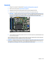
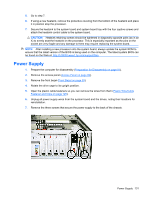
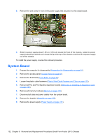
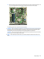
5. Go to step 7. 6. If using a new heatsink, remove the protective covering from the bottom of the heatsink and place it in position atop the processor. 7. Secure the heatsink to the system board and system board tray with the four captive screws and attach the heatsink control cable to the system board. CAUTION: Heatsink retaining screws should be tightened in diagonally opposite pairs (as in an X) to evenly seat the heatsink on the processor. This is especially important as the pins on the socket are very fragile and any damage to them may require replacing the system board. NOTE: After installing a new processor onto the system board, always update the system ROM to ensure that the latest version of the BIOS is being used on the computer. The latest system BIOS can be found on the Web at: http://h18000.www1.hp.com/support/files. Power Supply 1. Prepare the computer for disassembly (Preparation for Disassembly on page 91). 2. Remove the access panel (Access Panel on page 92). 3. Remove the front bezel (Front Bezel on page 93). 4. Rotate the drive cage to its upright position. 5. Open the plastic cable fasteners so you can remove the wires from them (Plastic Wire/Cable Fastener and Clips on page 125). 6. Unplug all power supply wires from the system board and the drives, noting their locations for reinstallation. 7. Remove the three screws that secure the power supply to the back of the chassis. Power Supply 131
-
 1
1 -
2
-
3
-
4
-
5
-
6
-
7
-
8
-
9
-
10
-
11
-
12
-
13
-
14
-
15
-
16
-
17
-
18
-
19
-
20
-
21
-
22
-
23
-
24
-
25
-
26
-
27
-
28
-
29
-
30
-
31
-
32
-
33
-
34
-
35
-
36
-
37
-
38
-
39
-
40
-
41
-
42
-
43
-
44
-
45
-
46
-
47
-
48
-
49
-
50
-
51
-
52
-
53
-
54
-
55
-
56
-
57
-
58
-
59
-
60
-
61
-
62
-
63
-
64
-
65
-
66
-
67
-
68
-
69
-
70
-
71
-
72
-
73
-
74
-
75
-
76
-
77
-
78
-
79
-
80
-
81
-
82
-
83
-
84
-
85
-
86
-
87
-
88
-
89
-
90
-
91
-
92
-
93
-
94
-
95
-
96
-
97
-
98
-
99
-
100
-
101
-
102
-
103
-
104
-
105
-
106
-
107
-
108
-
109
-
110
-
111
-
112
-
113
-
114
-
115
-
116
-
117
-
118
-
119
-
120
-
121
-
122
-
123
-
124
-
125
-
126
-
127
-
128
-
129
-
130
-
131
-
132
-
133
-
134
-
135
-
 136
136 -
 137
137 -
 138
138 -
 139
139 -
 140
140 -
 141
141 -
 142
142 -
 143
143 -
 144
144 -
 145
145 -
 146
146 -
147
-
148
-
149
-
150
-
151
-
152
-
153
-
154
-
155
-
156
-
157
-
158
-
159
-
160
-
161
-
162
-
163
-
164
-
165
-
166
-
167
-
168
-
169
-
170
-
171
-
172
-
173
-
174
-
175
-
176
-
177
-
178
-
179
-
180
-
181
-
182
-
183
-
184
-
185
-
186
-
187
-
188
-
189
-
190
-
191
-
192
-
193
-
194
-
195
-
196
-
197
-
198
-
199
-
200
 |
 |
