Compaq dx7500 Service Reference Guide: HP Compaq dx7500 Business PC - Page 108
Installing Additional Drives, - hp small form factor
 |
View all Compaq dx7500 manuals
Add to My Manuals
Save this manual to your list of manuals |
Page 108 highlights
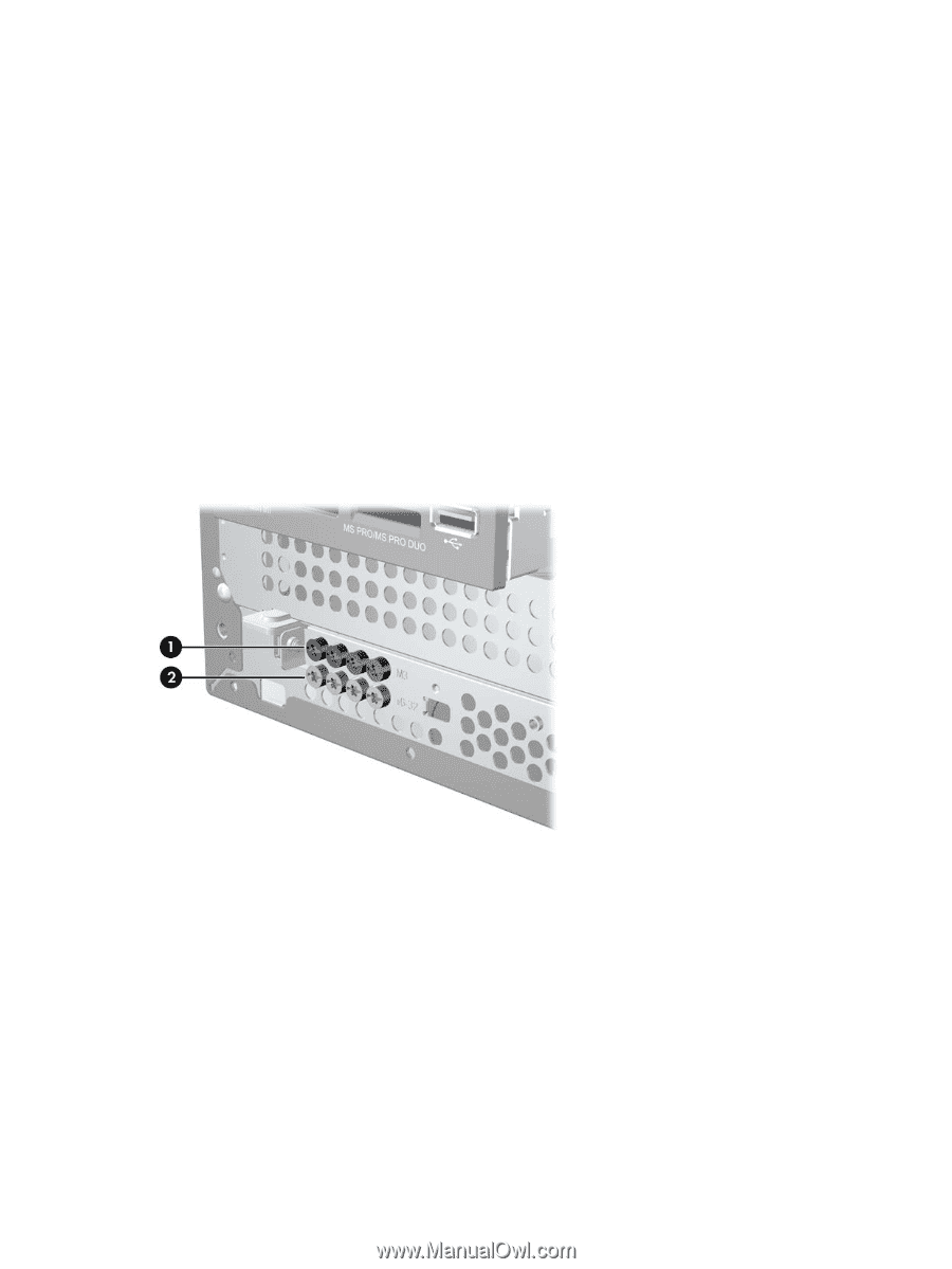
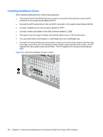
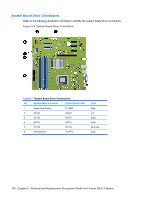
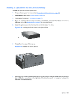
Installing Additional Drives When installing additional drives, follow these guidelines: ● The primary Serial ATA (SATA) hard drive must be connected to the dark blue primary SATA connector on the system board labeled SATA0. ● Connect the SATA optical drive to the red SATA connector on the system board labeled SATA4. ● Connect a diskette drive to the connector labeled FLOPPY. ● Connect a media card reader to the USB connector labeled F_USB2. ● The system does not support Parallel ATA (PATA) optical drives or PATA hard drives. ● You may install either a third-height or a half-height drive into a half-height bay. ● If needed, HP has provided extra drive retainer screws on the front of the chassis under the hard drive cage. Hard drives use 6-32 standard screws. All other drives use M3 metric screws. The HPsupplied M3 metric guide screws (1) are black. The HP-supplied 6-32 standard screws (2) are silver. Figure 8-5 Extra Drive Retainer Screws Location 98 Chapter 8 Removal and Replacement Procedures Small Form Factor (SFF) Chassis
-
 1
1 -
2
-
3
-
4
-
5
-
6
-
7
-
8
-
9
-
10
-
11
-
12
-
13
-
14
-
15
-
16
-
17
-
18
-
19
-
20
-
21
-
22
-
23
-
24
-
25
-
26
-
27
-
28
-
29
-
30
-
31
-
32
-
33
-
34
-
35
-
36
-
37
-
38
-
39
-
40
-
41
-
42
-
43
-
44
-
45
-
46
-
47
-
48
-
49
-
50
-
51
-
52
-
53
-
54
-
55
-
56
-
57
-
58
-
59
-
60
-
61
-
62
-
63
-
64
-
65
-
66
-
67
-
68
-
69
-
70
-
71
-
72
-
73
-
74
-
75
-
76
-
77
-
78
-
79
-
80
-
81
-
82
-
83
-
84
-
85
-
86
-
87
-
88
-
89
-
90
-
91
-
92
-
93
-
94
-
95
-
96
-
97
-
98
-
99
-
100
-
101
-
102
-
 103
103 -
 104
104 -
 105
105 -
 106
106 -
 107
107 -
 108
108 -
 109
109 -
 110
110 -
 111
111 -
 112
112 -
 113
113 -
114
-
115
-
116
-
117
-
118
-
119
-
120
-
121
-
122
-
123
-
124
-
125
-
126
-
127
-
128
-
129
-
130
-
131
-
132
-
133
-
134
-
135
-
136
-
137
-
138
-
139
-
140
-
141
-
142
-
143
-
144
-
145
-
146
-
147
-
148
-
149
-
150
-
151
-
152
-
153
-
154
-
155
-
156
-
157
-
158
-
159
-
160
-
161
-
162
-
163
-
164
-
165
-
166
-
167
-
168
-
169
-
170
-
171
-
172
-
173
-
174
-
175
-
176
-
177
-
178
-
179
-
180
-
181
-
182
-
183
-
184
-
185
-
186
-
187
-
188
-
189
-
190
-
191
-
192
-
193
-
194
-
195
-
196
-
197
-
198
-
199
-
200
 |
 |