Compaq dx7500 Service Reference Guide: HP Compaq dx7500 Business PC - Page 142
Front Bezel, Disconnect all data and power cables from the system board.
 |
View all Compaq dx7500 manuals
Add to My Manuals
Save this manual to your list of manuals |
Page 142 highlights
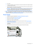
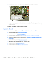
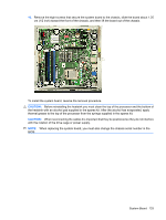
8. Remove the one screw in front of the power supply that secures it to the chassis base. 9. Slide the power supply about 1.25 cm (1/2-inch) toward the front of the chassis, rotate the power supply toward the heatsink so it clears the lip at the top of the chassis, and then lift the power supply out of the chassis. To install the power supply, reverse the removal procedure. System Board 1. Prepare the computer for disassembly (Preparation for Disassembly on page 91). 2. Remove the access panel (Access Panel on page 92). 3. Remove the front bezel (Front Bezel on page 93). 4. Loosen the plastic cable fasteners (Plastic Wire/Cable Fastener and Clips on page 125). 5. Remove all PCI and PCI Express expansion boards (Removing or Installing an Expansion Card on page 120). 6. Remove all memory modules (Memory on page 115). 7. Disconnect all data and power cables from the system board. 8. Remove the heatsink (Heatsink on page 129). 9. Remove the power supply (Power Supply on page 131). 132 Chapter 8 Removal and Replacement Procedures Small Form Factor (SFF) Chassis
-
 1
1 -
2
-
3
-
4
-
5
-
6
-
7
-
8
-
9
-
10
-
11
-
12
-
13
-
14
-
15
-
16
-
17
-
18
-
19
-
20
-
21
-
22
-
23
-
24
-
25
-
26
-
27
-
28
-
29
-
30
-
31
-
32
-
33
-
34
-
35
-
36
-
37
-
38
-
39
-
40
-
41
-
42
-
43
-
44
-
45
-
46
-
47
-
48
-
49
-
50
-
51
-
52
-
53
-
54
-
55
-
56
-
57
-
58
-
59
-
60
-
61
-
62
-
63
-
64
-
65
-
66
-
67
-
68
-
69
-
70
-
71
-
72
-
73
-
74
-
75
-
76
-
77
-
78
-
79
-
80
-
81
-
82
-
83
-
84
-
85
-
86
-
87
-
88
-
89
-
90
-
91
-
92
-
93
-
94
-
95
-
96
-
97
-
98
-
99
-
100
-
101
-
102
-
103
-
104
-
105
-
106
-
107
-
108
-
109
-
110
-
111
-
112
-
113
-
114
-
115
-
116
-
117
-
118
-
119
-
120
-
121
-
122
-
123
-
124
-
125
-
126
-
127
-
128
-
129
-
130
-
131
-
132
-
133
-
134
-
135
-
136
-
 137
137 -
 138
138 -
 139
139 -
 140
140 -
 141
141 -
 142
142 -
 143
143 -
 144
144 -
 145
145 -
 146
146 -
 147
147 -
148
-
149
-
150
-
151
-
152
-
153
-
154
-
155
-
156
-
157
-
158
-
159
-
160
-
161
-
162
-
163
-
164
-
165
-
166
-
167
-
168
-
169
-
170
-
171
-
172
-
173
-
174
-
175
-
176
-
177
-
178
-
179
-
180
-
181
-
182
-
183
-
184
-
185
-
186
-
187
-
188
-
189
-
190
-
191
-
192
-
193
-
194
-
195
-
196
-
197
-
198
-
199
-
200
 |
 |
