Craftsman 22901 Instruction Manual - Page 12
See
 |
View all Craftsman 22901 manuals
Add to My Manuals
Save this manual to your list of manuals |
Page 12 highlights
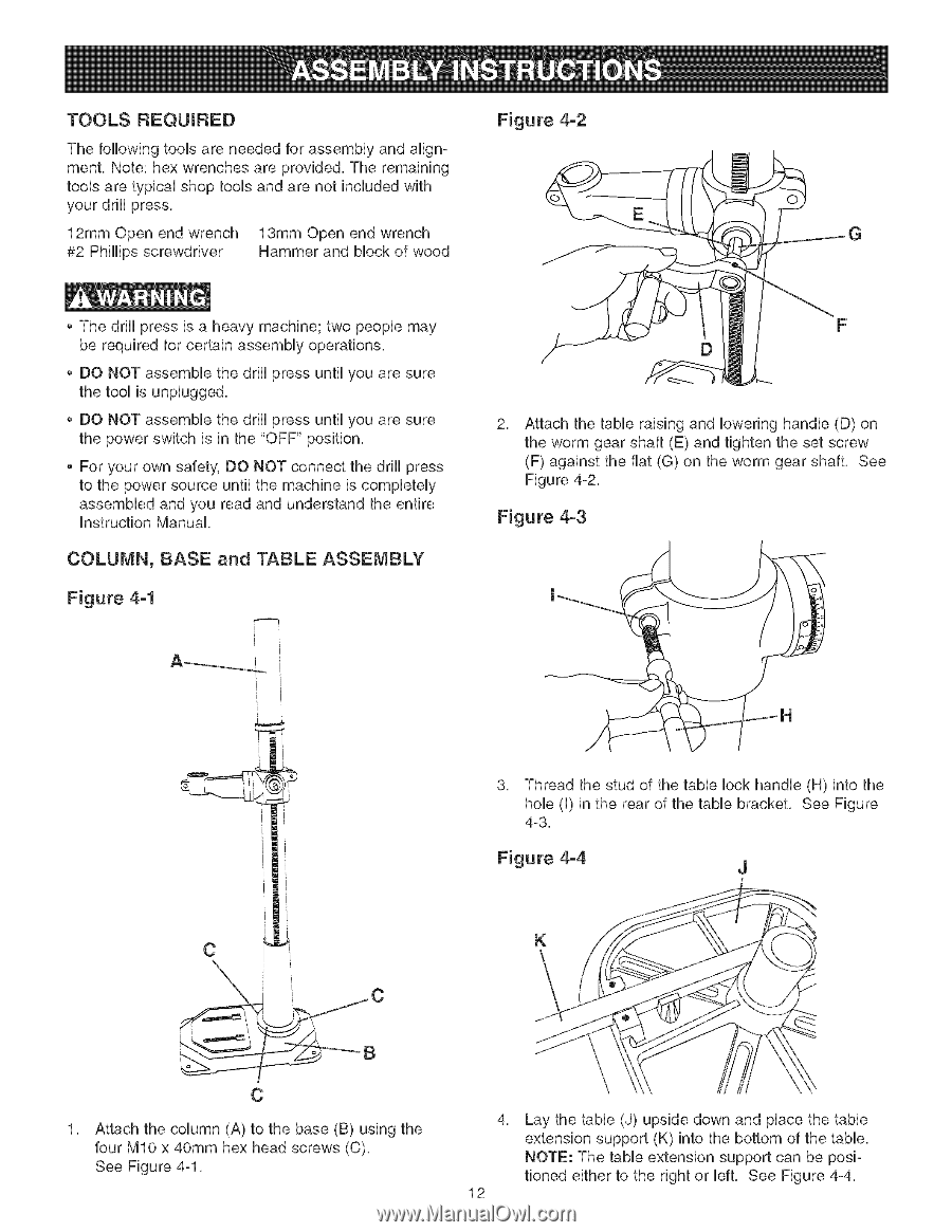
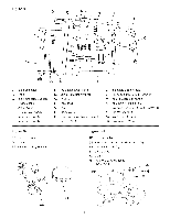
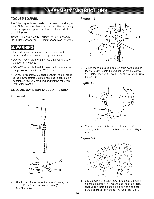
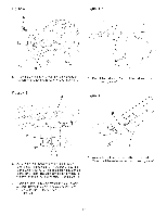
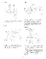
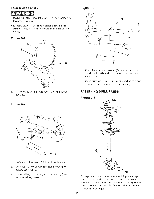
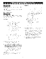
TOOLS REQUIRED The following toob are needed for assemMy and alignment. Note: hex wrenches are provided. The remaining toob are typbaU shop tooUsand are not included with your drHUpress. 12mm Open end wrench 13mm Open end wrench #2 PhHHpsscrewdriver Hammer and Mock of wood Figure 4-2 O G The drHUpress is a heavy machine; two peopb may be required for certain assemMy operations. DO NOT assembb the drHUpress until you are sure the tooUis unpUugged. DO NOT assembb the drHUpress until you are sure the power switch is in the "OFF" position. For your own safety, DO NOT connect the drHUpress to the power source until the machine is completely assembled and you read and understand the entire Instruction Manual. COLUMN, BASE and TABLE ASSEMBLY Figure 4-1 i [ 2, Attach the table raising and lowering handle (D) on the worm gear shaft (E) and tighten the set screw (F) against the fiat (G) on the worm gear shaft, See Figure 4-2, Figure 4-3 3. Thread the stud of the table lock handle (H) into the hob (I) in the rear of the table bracket. See Figure 4-3. Figure 4-4 J K Attach the column (A) to the base (B) using the four MIO x 40mm hex head screws (C). See Figure 4-1. 4, 12 Lay the table (J) upside down and place the table extension support (K) into the bottom of the table. NOTE: The table extension support can be positioned either to the right or left. See Figure 4-4.
-
 1
1 -
2
-
3
-
4
-
5
-
6
-
 7
7 -
 8
8 -
 9
9 -
 10
10 -
 11
11 -
 12
12 -
 13
13 -
 14
14 -
 15
15 -
 16
16 -
 17
17 -
18
-
19
-
20
-
21
-
22
-
23
-
24
-
25
-
26
-
27
-
28
-
29
-
30
-
31
-
32
-
33
-
34
-
35
-
36
-
37
-
38
-
39
-
40
-
41
-
42
-
43
-
44
-
45
-
46
-
47
-
48
-
49
-
50
-
51
-
52
-
53
-
54
-
55
-
56
-
57
-
58
-
59
-
60
 |
 |