Craftsman 22901 Instruction Manual - Page 19
so 00d, B0,d ,°0d
 |
View all Craftsman 22901 manuals
Add to My Manuals
Save this manual to your list of manuals |
Page 19 highlights
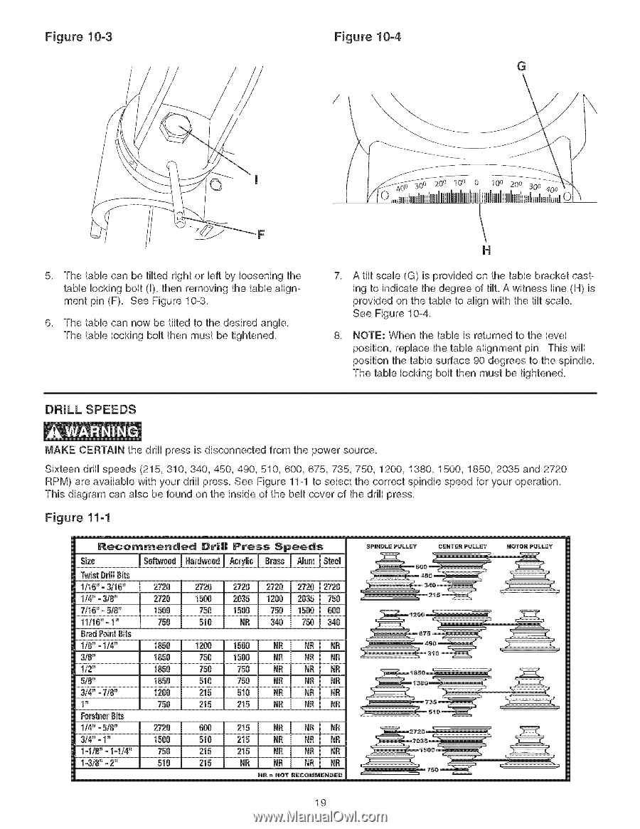
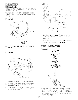
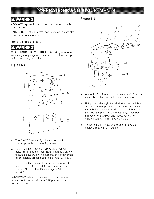
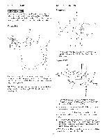
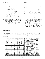
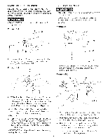
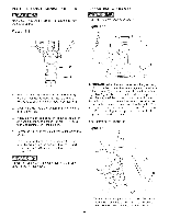
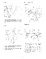
Figure 10-3 Figure 10-4 G 20 o 100 0 10° 200 300 5, The tame can be tilted right or Ueftby Uoosening the tame Uocking bout (U),then removing the tame alignment pin (F), See Figure 10-3, 6, The tame can now be tilted to the desired angUe, The tame Uocking bout then must be tightened, DRILL SPEEDS H 7, A tilt scaUe (G) is provided on the tame bracket casting to indicate the degree of tilt, A witness Hne (H) is provided on the tame to align with the tilt scaUe, See Figure 10-4, 8, NOTE: When the tame is returned to the UeveU position, repUace the tame alignment pin, This will position the table surface 90 degrees to the spindle, The table locking bolt then must be tightened, MAKE CERTAIN the drill press is disconnected from the power source, Sixteen drill speeds (215, 310,340, 450, 490, 510, 600, 675,735, 750, 1200, 1380, 1500, 1850, 2035 and 2720 RPM) are available with your drill press, See Figure 11-1 to select the correct spindle speed for your operation, This diagram can also be found on the inside of the belt cover of the drill press, Figure 11-1 Recommended Dri|| Press Speeds 6P|H6LE PULLEY s ,o !so 00IdB0,d I,°00,dy,I0B 0I°.,.mIst001 600 TwisDt rillBits _45 1/1B"=3/1B" 2720 2720 2720 2728 2720 2720 1t4"- 3/8" 2728 1500 2835 !200 2835 750 7/1B"=5/8" 1580 750 1500 758 1500 BOO 11116=" 1" 750 5!B NR 340 750 340 BradPeinBt its 1/8"- 1/4" 1850 1208 1500 N£ NR NR 3/8" 1850 750 1500 NR NR NR 1/2" 1850 758 750 NR NR NR 5/8" 1850 518 750 NR BR NR 3/4"o7/8" 1280 215 510 NR NR NR 1_ 750 215 215 NR NR NB FerstneBr its 1/4"=5/8" 2720 BOB 215 NR NR NR 3/4"=1" 1580 510 215 NR NR NR 1ol/8"=1ol/4" 750 215 215 N£ NR NR 1o3/8"=2" 510 215 NR NR NR NR NR = NOT R6COMMEN#E# CENTE6 PULLEY _OTOR PULLEY 19
-
 1
1 -
2
-
3
-
4
-
5
-
6
-
7
-
8
-
9
-
10
-
11
-
12
-
13
-
 14
14 -
 15
15 -
 16
16 -
 17
17 -
 18
18 -
 19
19 -
 20
20 -
 21
21 -
 22
22 -
 23
23 -
 24
24 -
25
-
26
-
27
-
28
-
29
-
30
-
31
-
32
-
33
-
34
-
35
-
36
-
37
-
38
-
39
-
40
-
41
-
42
-
43
-
44
-
45
-
46
-
47
-
48
-
49
-
50
-
51
-
52
-
53
-
54
-
55
-
56
-
57
-
58
-
59
-
60
 |
 |