Craftsman 22901 Instruction Manual - Page 22
side Uaser, See
 |
View all Craftsman 22901 manuals
Add to My Manuals
Save this manual to your list of manuals |
Page 22 highlights
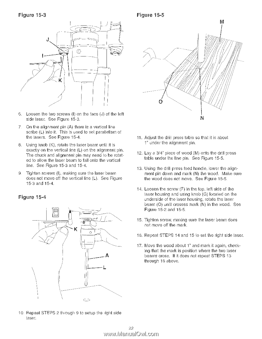
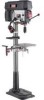
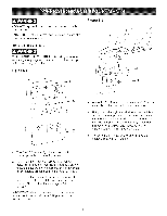
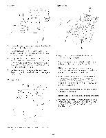
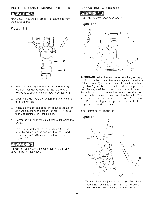
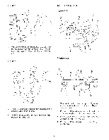
Figure 15-3 Figure 15-5 M J J 6, Loosen the two screws (U)on the face (J) of the bft side Uaser, See Figure 15-3, 7, On the alignment pin (A) there is a verticaU fine scribe (L) into it, This is used to set parafleHsm of the Uasers, See Figure 15-4, 8, Using knob (K), rotate the Uaser beam untiU it is exactly on the vertbaU Hne (L) on the alignment pin, The chuck and alignment pin may need to be rotated to aflow the Uaser beam to fail onto the vertbaU Hne, See Figure 15-3 and 15-4, 9, Tighten screws (U), making sure the Uaser beam does not move off the vertbaU line (L), See Figure 15-3 and 15-4, Figure 15-4 K 11, Adjust the drill press table so that it is about 1" under the alignment pin, 12, Lay a 3/4" piece of wood (M) onto the drill press table under the line pin, See Figure 15-5, 13, Using the drift press feed handle, lower the alignment pin down and mark (N) the wood, Make sure the wood does not move, See Figure 15-5, 14, Loosen the screw (F) in the top, left side of the laser housing and using knob (G) located on the underside of the laser housing, rotate the laser beam (0) until crosses mark (N) in the wood, See Figure 15-2 and 15-5, 15, Tighten screw, making sure the laser beam does not move off the mark, 16, Repeat STEPS 14 and 15 to set the right side laser, 17, Move the wood about 1" and mark it again, checking that the mark is position where the two laser beams cross, if it does not repeat STEPS 13 through 16 above, \ \ 10, Repeat STEPS 2 through 9 to setup the right side laser, 22
-
 1
1 -
2
-
3
-
4
-
5
-
6
-
7
-
8
-
9
-
10
-
11
-
12
-
13
-
14
-
15
-
16
-
 17
17 -
 18
18 -
 19
19 -
 20
20 -
 21
21 -
 22
22 -
 23
23 -
 24
24 -
 25
25 -
 26
26 -
 27
27 -
28
-
29
-
30
-
31
-
32
-
33
-
34
-
35
-
36
-
37
-
38
-
39
-
40
-
41
-
42
-
43
-
44
-
45
-
46
-
47
-
48
-
49
-
50
-
51
-
52
-
53
-
54
-
55
-
56
-
57
-
58
-
59
-
60
 |
 |