Craftsman 22901 Instruction Manual - Page 6
Do Not Modify The Plug Provided.
 |
View all Craftsman 22901 manuals
Add to My Manuals
Save this manual to your list of manuals |
Page 6 highlights
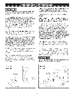
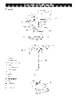
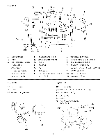
THINSTOOL MUST BE GROUNDED WHmLE mNUSE TO PROTECT THE OPERATOR FROM ELECTRmC SHOCK. mNTHE EVENT OF A MALFUNCTmON OR BREAKDOWN, grounding provides the path of Ueastresistance for eUectric current and reduces the risk of eUectric shock. This tooUis equipped with an eUectric cord that has an equipment-grounding conductor and a grounding pUug. The pUugMUST be pUugged into a matching eUectdcaUreceptacle that is propedy installed and grounded in accordance with ALL UocaUcodes and ordinances. DO NOT MODIFY THE PLUG PROVIDED. ff it wHUnot fit the eUectdcaUreceptacUe, have the proper eUectdcaU receptacle installed by a qualified electrician. IMPROPER ELECTRICAL CONNECTION of the equip° ment-grounding conductor can result in risk of electric shock. The conductor with the green insulation (with or without yellow stripes) is the equipment-grounding conductor. DO NOT connect the equipment-grounding conductor to a live terminal if repair or replacement of the electric cord or plug is necessary. CHECK with a qualified electrician or service personnel if you do not completely understand the grounding instructions, or if you are not sure the tool is properly grounded. The motor supplied with your Drill Press is a dual voltage 120/240 volts, 60 hertz alternating current, single phase motor, It is shipped wired for 120 volts application, Never connect the green or ground wire to a live terminal, USE ONLY A 3-WIRE EXTENSION CORD THAT HAS A 3-PRONG GROUNDING PLUG AND A 3-POLE RECEPTACLE THAT ACCEPTS THE TOOL'S PLUG. REPLACE A DAMAGED OR WORN CORD IMMEDIATELY. FOR GROUNDED, CORD-CONNECTED MACHINES INTENDED FOR USE ON A SUPPLY CIRCUIT HAVING A NOMINAL RATING LESS THAN 150 VOLTS. This tool is intended for use on a circuit that has an electrical receptacle as shown in FIGURE 1-1. FIGURE 1-1 shows a 3-wire electrical plug and electrical receptacle that has a grounding conductor. If a properly grounded electrical receptacle is not available, an adapter as shown in FIGURE 1-2 can be used to temporarily connect this plug to a 2-contact ungrounded receptacle. The adapter has a rigid lug extending from it that MUST be connected to a permanent earth ground, such as a properly grounded receptacle box. THIS ADAPTER IS PROHIBITED IN CANADA. CAUTION: In all cases, make certain the electrical receptacle in question is properly grounded. If you are not sure, have a certified electrician check the electrical receptacle. The motor supplied with your Drill Press is a dual voltage, 120/240 volt, single phase motor. If it is desired to operate your drill press at 240 volts, it is necessary to reconnect the motor leads in the motor junction box by following the wiring diagram on the junction box cover. MAKE CERTAIN the motor is disconnected from power source before reconnecting motor leads. Fig. 1-1 120 Volt grounding conductor 3-wire power cord 3-prong electrical receptacle Fig. 1-2 120 Volt grounding conductor grounding 3-wire power cord 2-prong electrical receptacle
-
 1
1 -
 2
2 -
 3
3 -
 4
4 -
 5
5 -
 6
6 -
 7
7 -
 8
8 -
 9
9 -
 10
10 -
 11
11 -
 12
12 -
13
-
14
-
15
-
16
-
17
-
18
-
19
-
20
-
21
-
22
-
23
-
24
-
25
-
26
-
27
-
28
-
29
-
30
-
31
-
32
-
33
-
34
-
35
-
36
-
37
-
38
-
39
-
40
-
41
-
42
-
43
-
44
-
45
-
46
-
47
-
48
-
49
-
50
-
51
-
52
-
53
-
54
-
55
-
56
-
57
-
58
-
59
-
60
 |
 |