Craftsman 22901 Instruction Manual - Page 14
See
 |
View all Craftsman 22901 manuals
Add to My Manuals
Save this manual to your list of manuals |
Page 14 highlights
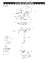
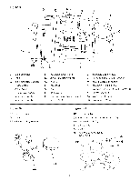
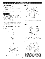
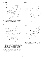
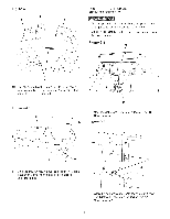
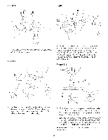
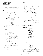
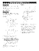
Figure 4-9 T X \ DRILL PRESS HEAD AND MOTOR ASSEMBLY The drHUpress is a heavy machine; two peopb may be required for certain assemMy operations, MAKE CERTAIN the drHUpress is disconnected from the power source, Figure 5-1 A V 10, LooseUy assembb the tray back (T) to the tray (U) with two pan head screws M5 x 35mm (V) and M5 hex nuts (X), See Figure 4-9, Figure 4-10 U B 1, Seat the drHUpress head (A) on the coUumn (B), See Figure 5-1, Figure 5-2 11, Slide the tray (U) down onto the column (A) until it rests on the ring (Y) and tighten both screws, See Figure 4-10 2, Align the drill press head with the table and base and tighten the two head locking screws (C), See Figure 5-2, 14
-
 1
1 -
2
-
3
-
4
-
5
-
6
-
7
-
8
-
 9
9 -
 10
10 -
 11
11 -
 12
12 -
 13
13 -
 14
14 -
 15
15 -
 16
16 -
 17
17 -
 18
18 -
 19
19 -
20
-
21
-
22
-
23
-
24
-
25
-
26
-
27
-
28
-
29
-
30
-
31
-
32
-
33
-
34
-
35
-
36
-
37
-
38
-
39
-
40
-
41
-
42
-
43
-
44
-
45
-
46
-
47
-
48
-
49
-
50
-
51
-
52
-
53
-
54
-
55
-
56
-
57
-
58
-
59
-
60
 |
 |
Figure
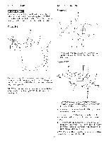
4-9
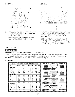
DRILL
PRESS
HEAD
AND
MOTOR
ASSEMBLY
X
\
T
The drHUpress is a heavy machine; two peopb
may
be required for certain
assemMy
operations,
MAKE
CERTAIN
the drHUpress is disconnected
from
the power source,
Figure
5-1
A
V
10, LooseUy assembb
the tray back (T) to the tray (U)
with two pan head screws
M5 x 35mm (V) and M5
hex nuts (X),
See Figure 4-9,
Figure
4-10
U
B
1,
Seat the drHUpress head (A) on the coUumn(B),
See Figure 5-1,
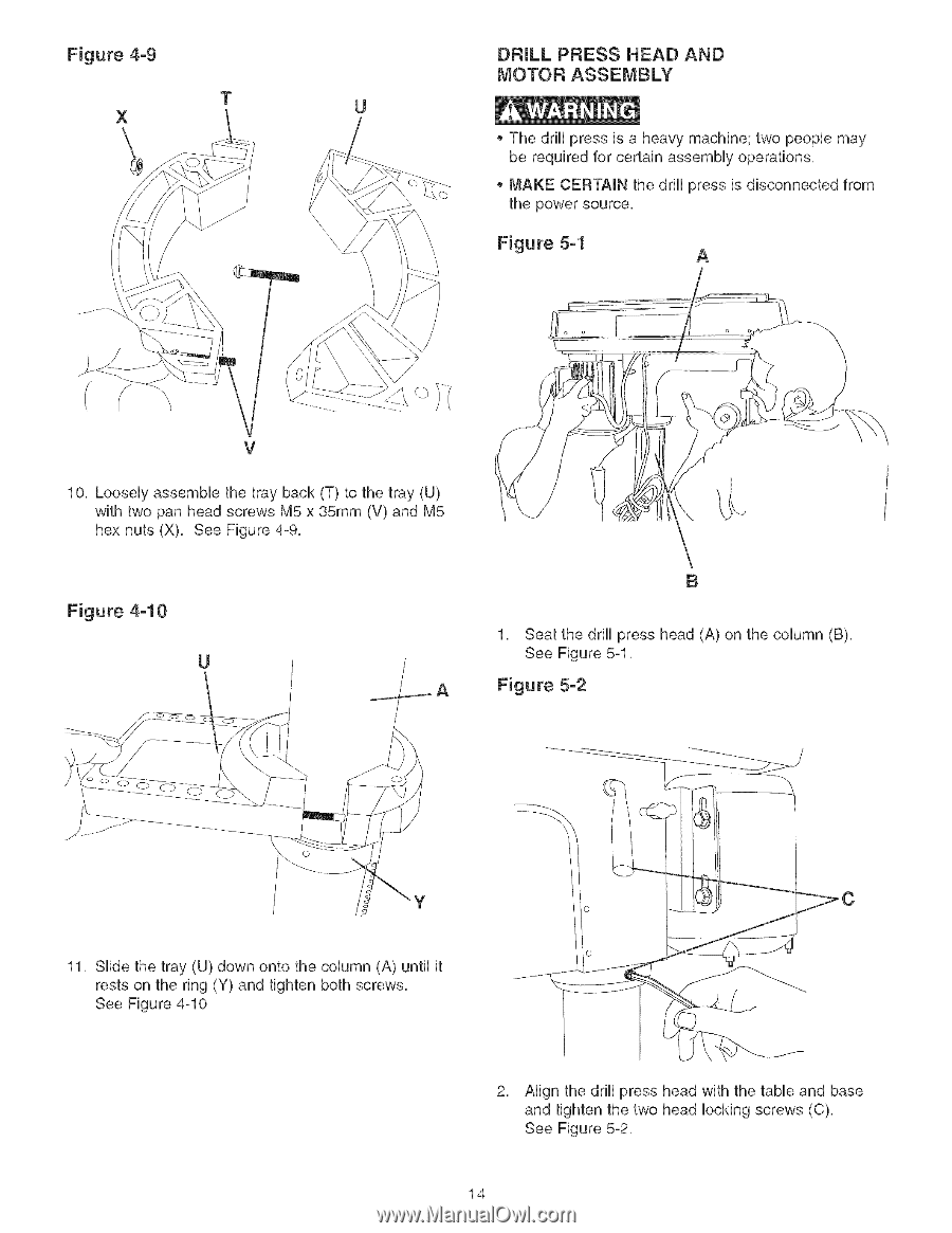
Figure
5-2
11, Slide the tray (U) down onto the column (A) until it
rests on the ring (Y) and tighten both screws,
See Figure 4-10
2,
Align the drill press head with the table and base
and tighten the two head locking screws (C),
See Figure 5-2,
14