Craftsman 22901 Instruction Manual - Page 16
Do Not Stare
 |
View all Craftsman 22901 manuals
Add to My Manuals
Save this manual to your list of manuals |
Page 16 highlights
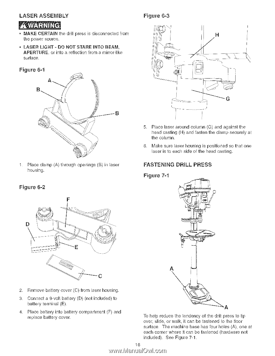
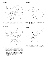
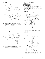
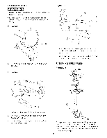
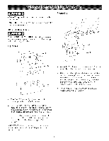
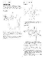
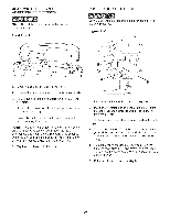
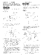
LASER ASSEMBLY MAKE CERTAIN the drill press is disconnected from the power source, LASER LIGHT - DO NOT STARE INTO BEAM, APERTURE, or into a reflection from a mirrorqke surface, Figure 6-1 Figure 6-3 1, Place clamp (A) through openings (B) in laser housing, Figure 6-2 F 5, Hace Uaser around coUumn (G) and against the head casting (H) and fasten the damp secureUy at the coUumn, 6, Make sure Uaser housing is positioned so that one Uaser is to each side of the head casting, D E \ C 2, Remove battery cover (C) from laser housing, 3, Connect a 9-volt battery (D) (not included) to battery terminal (E), 4, Place battery into battery compartment (F) and replace battery cover, A To help reduce the tendency of the drill press to tip over, slide, or walk, it can be fastened to the floor surface, The machine base has four hobs (A), one at each corner where it can be fastened (hardware not included), See Figure 7-1, 16
-
 1
1 -
2
-
3
-
4
-
5
-
6
-
7
-
8
-
9
-
10
-
 11
11 -
 12
12 -
 13
13 -
 14
14 -
 15
15 -
 16
16 -
 17
17 -
 18
18 -
 19
19 -
 20
20 -
 21
21 -
22
-
23
-
24
-
25
-
26
-
27
-
28
-
29
-
30
-
31
-
32
-
33
-
34
-
35
-
36
-
37
-
38
-
39
-
40
-
41
-
42
-
43
-
44
-
45
-
46
-
47
-
48
-
49
-
50
-
51
-
52
-
53
-
54
-
55
-
56
-
57
-
58
-
59
-
60
 |
 |