D-Link DSS-200G-28MP Product Manual - Page 123
Host IPv4 Address, Apply, Log Server, Password Settings, Password, Confirm Password, Uplink Port
 |
View all D-Link DSS-200G-28MP manuals
Add to My Manuals
Save this manual to your list of manuals |
Page 123 highlights
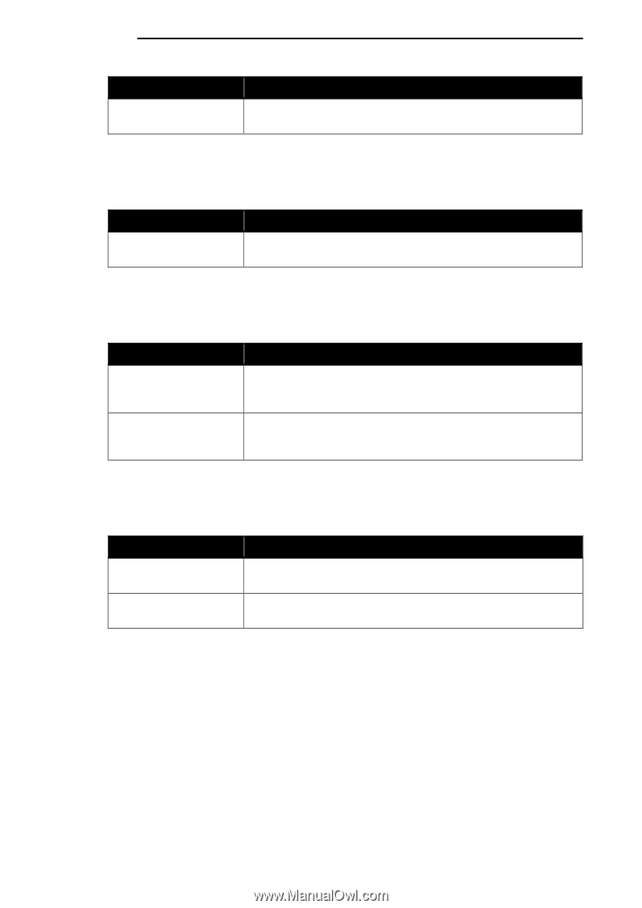
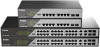
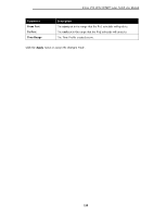
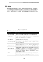
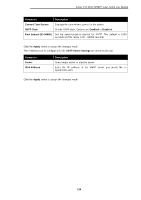
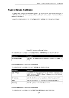
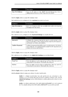
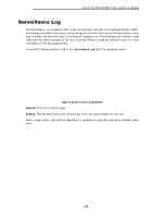
D-Link DSS-200G MP/MPP series Switch User Manual Parameter Host IPv4 Address Description Enter the IP address of the SNMP Network Management Server (NMS) which will receive SNMP Traps from this device. Click the Apply button to accept the changes made. The fields that can be configured for the Log Server are described below: Parameter Host IPv4 Address Description Enter the IP address of the Sys log NMS which will receive Sys log messages from this device. Click the Apply button to accept the changes made. The fields that can be configured for the Password Settings are described below: Parameter Password Confirm Password Description Configure the password that will be used to restrict access to the device via the Web UI. The password must contain 8 to 30 characters and include both letters and numbers. Confirm the password that will be used to restrict access to the device via the Web UI. The password must contain 8 to 30 characters and include both letters and numbers. Click the Apply button to accept the changes made. The fields that can be configured for the Uplink Port Settings are described below: Parameter From Port To Port Description Enter the start port in the range for Uplink Ports. These are used for connecting the surveillance VLAN with other switches. Enter the end port in the range for Uplink Ports. These are used for connecting the surveillance VLAN with other switches. Click the Apply button to accept the changes made. Click the Delete button to delete any entries in the list of uplink ports. NOTE: It is highly recommended that only uplink ports are connected to other switches, as the IP camera discovery process is disabled on these ports. Use the Uplink Port Settings section of the interface to define which ports connect to other switches. NOTE: The default uplink ports of the DSS-200G-10MP/10MPP are port 9 and port 10. The default uplink ports of DSS-200G-28MP/28MPP are port 25 to port 28. 118
-
 1
1 -
2
-
3
-
4
-
5
-
6
-
7
-
8
-
9
-
10
-
11
-
12
-
13
-
14
-
15
-
16
-
17
-
18
-
19
-
20
-
21
-
22
-
23
-
24
-
25
-
26
-
27
-
28
-
29
-
30
-
31
-
32
-
33
-
34
-
35
-
36
-
37
-
38
-
39
-
40
-
41
-
42
-
43
-
44
-
45
-
46
-
47
-
48
-
49
-
50
-
51
-
52
-
53
-
54
-
55
-
56
-
57
-
58
-
59
-
60
-
61
-
62
-
63
-
64
-
65
-
66
-
67
-
68
-
69
-
70
-
71
-
72
-
73
-
74
-
75
-
76
-
77
-
78
-
79
-
80
-
81
-
82
-
83
-
84
-
85
-
86
-
87
-
88
-
89
-
90
-
91
-
92
-
93
-
94
-
95
-
96
-
97
-
98
-
99
-
100
-
101
-
102
-
103
-
104
-
105
-
106
-
107
-
108
-
109
-
110
-
111
-
112
-
113
-
114
-
115
-
116
-
117
-
 118
118 -
 119
119 -
 120
120 -
 121
121 -
 122
122 -
 123
123 -
 124
124 -
 125
125 -
 126
126 -
 127
127 -
 128
128 -
129
-
130
-
131
-
132
-
133
-
134
-
135
-
136
 |
 |