Dell 1815dn Service Manual - Page 31
Output Control Signal BIAS-PWM : the CPU is HV output when PWM is low .
 |
UPC - 000061100008
View all Dell 1815dn manuals
Add to My Manuals
Save this manual to your list of manuals |
Page 31 highlights
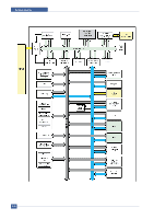
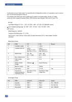
System Outline Charge Voltage (MHV) Input Voltage : 24 V DC 15% Output Voltage : -1.2KV ~ -1.8KV DC 3% Output Voltage Rising Time : 50 ms Max Output Voltage Falling Time : 50 ms Max Output Control Signal(MHV-PWM) : CPU is HV output when PWM is Low Cleaning Voltage (THV-) The (+) Transfer Voltage is not outputted because the THV PWM is controlled with high. The (-) Transfer Voltage is outputted because the THV-Enable Signal is controlled with low The output fluctuation range is big because there is no Feedback control. Developing Voltage (DEV) Input Voltage : 24 V DC 15% Output Voltage: -200V ~ -600V DC 3% Output Voltage Fluctuation Method : PWM Control Line Regulation : under 3% (fluctuation input 21.6V ~ 27.6V) Load Regulation : Under 3% Output Voltage Rising Time : 50 ms Max Output Voltage Falling Time : 50 ms Max Output Control Signal (BIAS-PWM) : the CPU output is HV output when PWM is low . Supply Output Voltage : -300V ~ -800V DC 5% (ZENER using, DEV ) Line Regulation : under 3% (fluctuation input 21.6V ~ 27.6V) Load Regulation : Under 3% Output Voltage Rising Time : 50 ms Max Output Voltage Falling Time : 50 ms Max Output Control Signal (BIAS-PWM) : the CPU is HV output when PWM is low . Service Manual 4-13
-
 1
1 -
2
-
3
-
4
-
5
-
6
-
7
-
8
-
9
-
10
-
11
-
12
-
13
-
14
-
15
-
16
-
17
-
18
-
19
-
20
-
21
-
22
-
23
-
24
-
25
-
 26
26 -
 27
27 -
 28
28 -
 29
29 -
 30
30 -
 31
31 -
 32
32 -
 33
33 -
 34
34 -
 35
35 -
 36
36 -
37
-
38
-
39
-
40
-
41
-
42
-
43
-
44
-
45
-
46
-
47
-
48
-
49
-
50
-
51
-
52
-
53
-
54
-
55
-
56
-
57
-
58
-
59
-
60
-
61
-
62
-
63
-
64
-
65
-
66
-
67
-
68
-
69
-
70
-
71
-
72
-
73
-
74
-
75
-
76
-
77
-
78
-
79
-
80
-
81
-
82
-
83
-
84
-
85
-
86
-
87
-
88
-
89
-
90
-
91
-
92
-
93
-
94
-
95
-
96
-
97
-
98
-
99
-
100
-
101
-
102
-
103
-
104
-
105
-
106
-
107
-
108
-
109
-
110
-
111
-
112
-
113
-
114
-
115
-
116
-
117
-
118
-
119
-
120
-
121
-
122
-
123
-
124
-
125
-
126
-
127
-
128
-
129
-
130
-
131
-
132
-
133
-
134
-
135
-
136
-
137
-
138
-
139
-
140
-
141
-
142
-
143
-
144
-
145
-
146
-
147
-
148
-
149
-
150
-
151
-
152
 |
 |