Dell 1815dn Service Manual - Page 88
Detail DescriptionEngine Test Mode, Laser Leady is displayed, When the Laser Scanning
 |
UPC - 000061100008
View all Dell 1815dn manuals
Add to My Manuals
Save this manual to your list of manuals |
Page 88 highlights
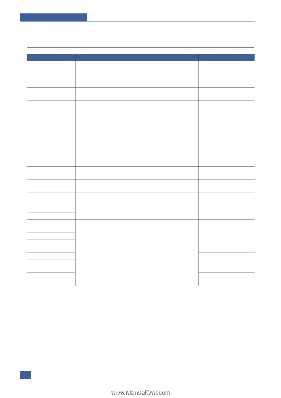
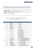
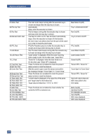
Alignment & Adjustments 6.5.3 Detail Description(Engine Test Mode) Function Name 01.Motor Test 02.Pick Up Test 03.Fan Test 04.Manual Clutch Test 05.PTL Test 11.LSU Motor 12.LSU Hsync Test 13.LD Test 21.Feed Sen Test 22.Exit Sen Test 23.Cover Sen Test 24.Empty Sen Test 25.Manual Sen Test 31.Them ADC 180 32.Them ADC 140 33.Them ADC 120 34.Them ADC 100 41.MHV Test 42.Dev Bias Test 43.THV EN/NEG Test 44.THV ON(1300V) 45.THV ADC 1300V 46.THV ADC 600V~3500 Description The main motor keeps running after the execution key is chosen and stops when the stop key is chosen. automatically stops, when the execution is chosen. The fan keeps running after the execution key is chosen and stops when the stop key is chosen. The tray2,3 clutch is on for 1sec and then it automatically stops, when the execution is chosen.On this function, the main motor runs before 2sec from the point of the clutch on in order to check the clutch state. PTL(Pre-Transfer Lamp) is on after the execution key is chosen and it stops when the stop key is chosen. Test The laser motor keeps running after the execution key is chosen and stops when the stop key is chosen. "Laser Leady" is displayed, When the Laser Scanning Unit is ready to print. On the other case "Laser Error" "Diode On" is displayed, when the laser diode is on. On the other case "Diode Off" is displayed. These Functions are considered to check the present state (normal or not)of the Sensors. After the cover is open, touch the sensor and confirm the message changed "Cover Open" to " Cover Close" These Functions are considered to check the present state (normal or not)of the Sensors. "current value"is displayed on the upper line of the panel, and "target value"on the bottom line. Target value is limited from "191°C" to "80°C" These Functions are considered to check whether the control for HVPS is normal or not. Display Main Motor On(Off) Tray 1,2 Solenoid On/Off Fan On(Off) Tray 2,3 Clutch On/Off PTL On(Off) Laser Motor On(Off) Laser Leady On(Off) Diode On(Off) "Sensor Off"to " Sensor On " "Cover Open" to "Cover Close" "Sensor Off"to " Sensor On " Input and output value are ADC value.(refer to the ADC table) MHV On(Off) Dev Bias On(Off) THV EN/NEG On(Off) THV On(Off) ADC value displayed. ADC value displayed. 6-18 Service Manual
-
 1
1 -
2
-
3
-
4
-
5
-
6
-
7
-
8
-
9
-
10
-
11
-
12
-
13
-
14
-
15
-
16
-
17
-
18
-
19
-
20
-
21
-
22
-
23
-
24
-
25
-
26
-
27
-
28
-
29
-
30
-
31
-
32
-
33
-
34
-
35
-
36
-
37
-
38
-
39
-
40
-
41
-
42
-
43
-
44
-
45
-
46
-
47
-
48
-
49
-
50
-
51
-
52
-
53
-
54
-
55
-
56
-
57
-
58
-
59
-
60
-
61
-
62
-
63
-
64
-
65
-
66
-
67
-
68
-
69
-
70
-
71
-
72
-
73
-
74
-
75
-
76
-
77
-
78
-
79
-
80
-
81
-
82
-
 83
83 -
 84
84 -
 85
85 -
 86
86 -
 87
87 -
 88
88 -
 89
89 -
 90
90 -
 91
91 -
 92
92 -
 93
93 -
94
-
95
-
96
-
97
-
98
-
99
-
100
-
101
-
102
-
103
-
104
-
105
-
106
-
107
-
108
-
109
-
110
-
111
-
112
-
113
-
114
-
115
-
116
-
117
-
118
-
119
-
120
-
121
-
122
-
123
-
124
-
125
-
126
-
127
-
128
-
129
-
130
-
131
-
132
-
133
-
134
-
135
-
136
-
137
-
138
-
139
-
140
-
141
-
142
-
143
-
144
-
145
-
146
-
147
-
148
-
149
-
150
-
151
-
152
 |
 |