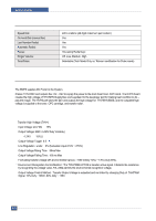
Dell 1815dn Service Manual - Page 33
UL1950, CSA950, C-UL, NOM, TUV, Semko, EK, CB, GOST, EPA, Power save
 |
UPC - 000061100008
View all Dell 1815dn manuals
Add to My Manuals
Save this manual to your list of manuals |
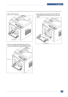
Page 33 highlights
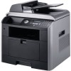
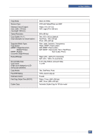
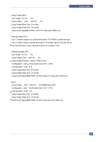
System Outline Length of Power Cord : 1830 50mm Power Switch : Use Feature Insulating Resistance : 100 or more (at DC 500V) Withstanding Voltage : Must be no problem within 1 min. (at 1000V -LV model / 1500Vac-HV model,10mA) Leaking Current : under 3.5mA Running Current : under 40A PEAK (AT 25 , COLD START) under 60A PEAK (In other conditions) Rising Time : within 2Sec Falling Time : over 20ms Surge : Bi-Wave 3kV ? Normal, 6KV - Common Environment Condition Operating temperature range : 0 40 Maintaining temperature range : -25 85 Preserving Humidity Condition : 30% 90% RH Operating atmospheric pressure range : 1atm EMI Requirement : CISPR ,FCC, CE, MIC Safety Requrement :IEC950 UL1950, CSA950, C-UL,NOM,TUV,Semko,EK,CB, GOST, EPA, Power save FUSER AC POWER CONTROL Fuser(HEAT LAMP) gets heat from AC power. The AV power controls the switch with the Triac, a semiconductor switch. The ON/OFF control is operated when the gate of the Triac is turned on/off by Phototriac (insulting part). In other words, the AC control part is passive circuit, so it turns the heater on/of f with taking signal from engine control part. When the HEATER ON signal is turned on at engine, the LED of PC501 (Photo Triac) takes the voltage and flashes. From the flashing light, the Triac part (light receiving part) takes the voltage, and the voltage is supplied to the gate of Triac and flows into the Triac. As a result, the AC current flows in the heat lamp, and heat is occurred. On the other hand, when the signal is of f, the PC501 is off, the voltage is cut off at the gate of Triac, the Triac becomes off, and then the heat lamp is turned of f. Triac (Q501) feature : 24A-LV model / 16A-HV model, 600V SWITCHING Phototriac Coupler (PC501) Turn On If Current : 15mA 50mA(Design: 16mA) High Repetive Peak Off State Voltage : Min 600V Service Manual 4-15
-
 1
1 -
2
-
3
-
4
-
5
-
6
-
7
-
8
-
9
-
10
-
11
-
12
-
13
-
14
-
15
-
16
-
17
-
18
-
19
-
20
-
21
-
22
-
23
-
24
-
25
-
26
-
27
-
 28
28 -
 29
29 -
 30
30 -
 31
31 -
 32
32 -
 33
33 -
 34
34 -
 35
35 -
 36
36 -
 37
37 -
 38
38 -
39
-
40
-
41
-
42
-
43
-
44
-
45
-
46
-
47
-
48
-
49
-
50
-
51
-
52
-
53
-
54
-
55
-
56
-
57
-
58
-
59
-
60
-
61
-
62
-
63
-
64
-
65
-
66
-
67
-
68
-
69
-
70
-
71
-
72
-
73
-
74
-
75
-
76
-
77
-
78
-
79
-
80
-
81
-
82
-
83
-
84
-
85
-
86
-
87
-
88
-
89
-
90
-
91
-
92
-
93
-
94
-
95
-
96
-
97
-
98
-
99
-
100
-
101
-
102
-
103
-
104
-
105
-
106
-
107
-
108
-
109
-
110
-
111
-
112
-
113
-
114
-
115
-
116
-
117
-
118
-
119
-
120
-
121
-
122
-
123
-
124
-
125
-
126
-
127
-
128
-
129
-
130
-
131
-
132
-
133
-
134
-
135
-
136
-
137
-
138
-
139
-
140
-
141
-
142
-
143
-
144
-
145
-
146
-
147
-
148
-
149
-
150
-
151
-
152
 |
 |