Dell 1815dn Service Manual - Page 53
Shield Controller Ass'y, Side Cover Left Refer to 5.6.4
 |
UPC - 000061100008
View all Dell 1815dn manuals
Add to My Manuals
Save this manual to your list of manuals |
Page 53 highlights
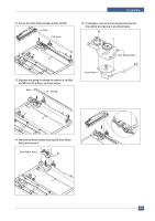
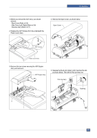
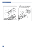
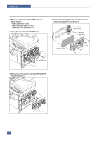
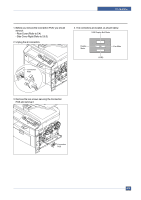
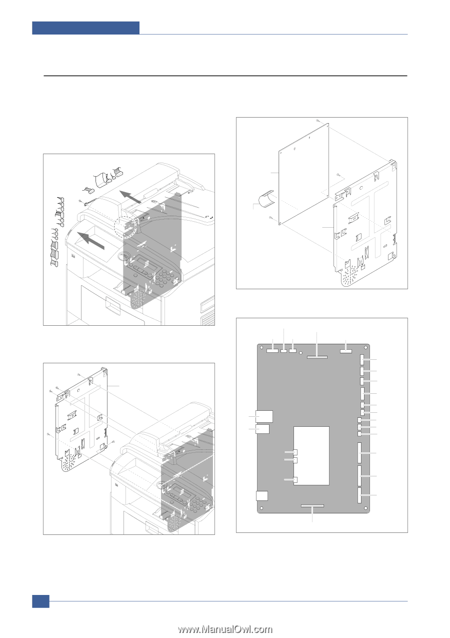
Precautions 5.10 Shield Controller Ass'y 1. Before you remove the Shield Controller Ass'y, you should remove: - Rear Cover (Refer to 5.4) - Side Cover Left (Refer to 5.6.4) 2. Unplug the all connectors and remove the one screw securing the Ground Cable. 4. Remove the three screws securing the Main PBA to the Bracket and unplug the Film Cable and then remove the Main PBA. Main PBA Film Cable Shield 3. Remove the five screws securing the Shield Controller Ass'y and remove it. Shield Controller Ass'y 5. The connectors are located, as shown below. Flat Cover CCD ADF Flat Motor OPE Panel USB Line Network USB Tray2 USB Host Cartridge LSU_5V LSU Thermo MPF_SEN MPF REGI Pick Up BLDG Engine Duplex Motor Modem PBA 5-18 Service Manual
-
 1
1 -
2
-
3
-
4
-
5
-
6
-
7
-
8
-
9
-
10
-
11
-
12
-
13
-
14
-
15
-
16
-
17
-
18
-
19
-
20
-
21
-
22
-
23
-
24
-
25
-
26
-
27
-
28
-
29
-
30
-
31
-
32
-
33
-
34
-
35
-
36
-
37
-
38
-
39
-
40
-
41
-
42
-
43
-
44
-
45
-
46
-
47
-
 48
48 -
 49
49 -
 50
50 -
 51
51 -
 52
52 -
 53
53 -
 54
54 -
 55
55 -
 56
56 -
 57
57 -
 58
58 -
59
-
60
-
61
-
62
-
63
-
64
-
65
-
66
-
67
-
68
-
69
-
70
-
71
-
72
-
73
-
74
-
75
-
76
-
77
-
78
-
79
-
80
-
81
-
82
-
83
-
84
-
85
-
86
-
87
-
88
-
89
-
90
-
91
-
92
-
93
-
94
-
95
-
96
-
97
-
98
-
99
-
100
-
101
-
102
-
103
-
104
-
105
-
106
-
107
-
108
-
109
-
110
-
111
-
112
-
113
-
114
-
115
-
116
-
117
-
118
-
119
-
120
-
121
-
122
-
123
-
124
-
125
-
126
-
127
-
128
-
129
-
130
-
131
-
132
-
133
-
134
-
135
-
136
-
137
-
138
-
139
-
140
-
141
-
142
-
143
-
144
-
145
-
146
-
147
-
148
-
149
-
150
-
151
-
152
 |
 |
Service Manual
Precautions
5-18
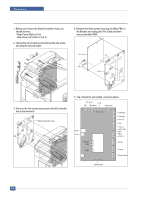
1. Before you remove the Shield Controller Ass'y, you
should remove:
- Rear Cover (Refer to 5.4)
- Side Cover Left (Refer to 5.6.4)
2. Unplug the all connectors and remove the one screw
securing the Ground Cable.
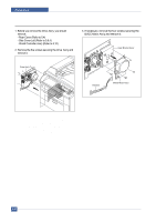
3. Remove the five screws securing the Shield Controller
Ass'y and remove it.
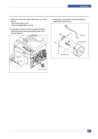
4. Remove the three screws securing the Main PBA
to
the Bracket and unplug the Film Cable and then
remove the Main PBA.
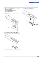
5. The connectors are located, as shown below.
5.10 Shield Controller Ass'y
Shield
Film Cable
Main PBA
ADF
Flat Motor
Flat Cover
CCD
OPE Panel
USB Host
Cartridge
USB
Line
Modem PBA
Duplex Motor
Engine
BLDG
Pick Up
REGI
LSU_5V
LSU
Thermo
MPF_SEN
MPF
Network
USB
Tray2
Shield Controller Ass'y