Dell 1815dn Service Manual - Page 58
Connection PCB
 |
UPC - 000061100008
View all Dell 1815dn manuals
Add to My Manuals
Save this manual to your list of manuals |
Page 58 highlights
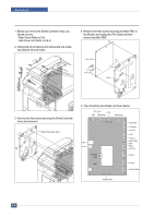
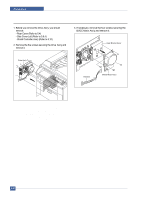
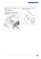
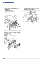
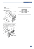
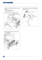
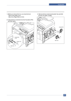
Precautions 5.14 Connection PCB 1. Before you remove the Connection PCB, you should remove: - Rear Cover (Refer to 5.4) - Side Cover Right (Refer to 5.6.3) 2. Unplug the all connectors. 4. The connectors are located, as shown below. FAN Duplex Exit Motor Duplex Motor HVPS Fan Main Connection PCB 3. Remove the two screws securing the Connection PCB and remove it. Connection PCB Service Manual 5-23
-
 1
1 -
2
-
3
-
4
-
5
-
6
-
7
-
8
-
9
-
10
-
11
-
12
-
13
-
14
-
15
-
16
-
17
-
18
-
19
-
20
-
21
-
22
-
23
-
24
-
25
-
26
-
27
-
28
-
29
-
30
-
31
-
32
-
33
-
34
-
35
-
36
-
37
-
38
-
39
-
40
-
41
-
42
-
43
-
44
-
45
-
46
-
47
-
48
-
49
-
50
-
51
-
52
-
 53
53 -
 54
54 -
 55
55 -
 56
56 -
 57
57 -
 58
58 -
 59
59 -
 60
60 -
 61
61 -
 62
62 -
 63
63 -
64
-
65
-
66
-
67
-
68
-
69
-
70
-
71
-
72
-
73
-
74
-
75
-
76
-
77
-
78
-
79
-
80
-
81
-
82
-
83
-
84
-
85
-
86
-
87
-
88
-
89
-
90
-
91
-
92
-
93
-
94
-
95
-
96
-
97
-
98
-
99
-
100
-
101
-
102
-
103
-
104
-
105
-
106
-
107
-
108
-
109
-
110
-
111
-
112
-
113
-
114
-
115
-
116
-
117
-
118
-
119
-
120
-
121
-
122
-
123
-
124
-
125
-
126
-
127
-
128
-
129
-
130
-
131
-
132
-
133
-
134
-
135
-
136
-
137
-
138
-
139
-
140
-
141
-
142
-
143
-
144
-
145
-
146
-
147
-
148
-
149
-
150
-
151
-
152
 |
 |
Precautions
Service Manual
5-23
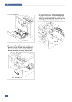
5.14 Connection PCB
1. Before you remove the Connection PCB, you should
remove:
- Rear Cover (Refer to 5.4)
- Side Cover Right (Refer to 5.6.3)
2. Unplug the all connectors.
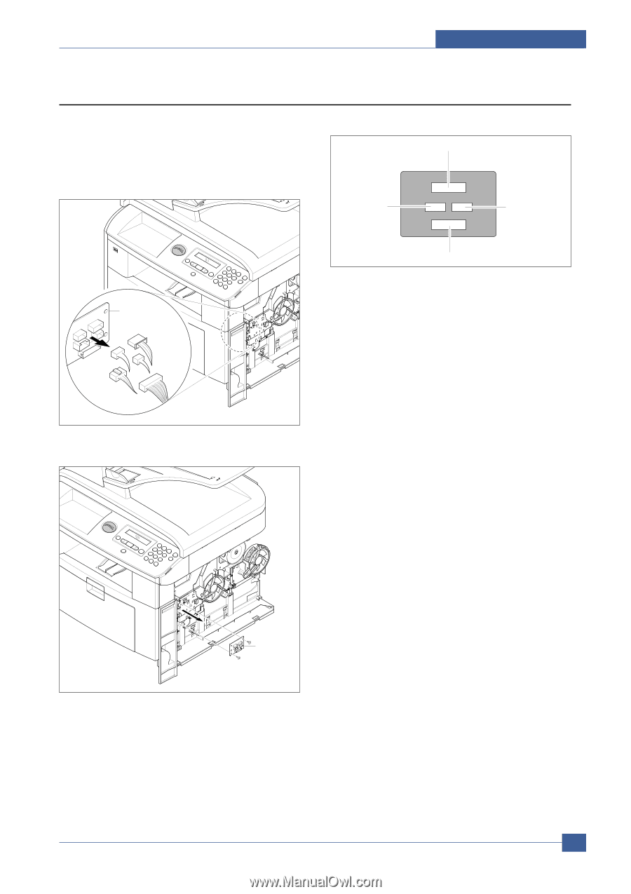
3. Remove the two screws securing the Connection
PCB and remove it.
4. The connectors are located, as shown below.
Connection
PCB
Connection
PCB
FAN Duplex Exit Motor
Fan Main
HVPS
Duplex
Motor