Dell 2405FPW User Manual - Page 18
Using the Front Panel Buttons, Component video Y Pb Pr input - inputs
 |
View all Dell 2405FPW manuals
Add to My Manuals
Save this manual to your list of manuals |
Page 18 highlights
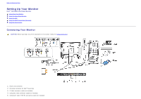
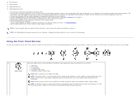
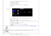
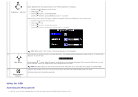
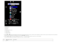
6 DVI connector 7 VGA connector 8 USB upstream port 9 USB downstream ports Turn off your computer and disconnect the power cable. Connect either the white (digital DVI-D) or the blue (analog D-sub) display connector cable to the corresponding video port on the back of your computer. Do not use both cables on the same computer. The only case in which both cables can be used is if they are connected to two different computers with appropriate video systems. (Graphics are for illustration only. System appearance may vary). Connect the upstream USB port (cable supplied) to an appropriate USB port on your computer . Connect USB peripherals to the downstream USB ports (rear or side) on the monitor. (See rear or bottom view for details.) Connect the DC power cable for your monitor to the power port on the back of the monitor. Plug the power cables for your computer and monitor into a nearby outlet. Turn on the monitor and computer. If your monitor displays an image, installation is complete. If it does not display an image, see Solving Problems. Use the cable holder on the monitor stand to neatly organize the cables. NOTE: If your computer does not support the DVI connector, you can leave the cable unconnected or remove it. NOTE: For USB peripherals already connected to your computer, changing the USB connection to your monitor is not necessary. Using the Front Panel Buttons Use the control buttons on the front of the monitor to adjust the characteristics of the image being displayed. As you use these buttons to adjust the controls, an OSD shows their numeric values as they change. A Use Input Select button to select between five different video signals that may be connected to your monitor. Input select 1. VGA input 2. DVI-D input 3. S- Video input 4. Composite video input 5. Component video (Y Pb Pr) input NOTE: VGA is referred to as D-SUB in the OSD NOTE: The floating 'Dell™ - self-test Feature Check' dialog will also appear on-screen (against a black background) if the monitor cannot sense a video signal. Depending upon the selected input, one of the dialogs shown below will scroll continually. NOTE: Self test feature check is not available for S-Video, Composite video and Component video (Y Pb Pr) modes. NOTE: If VGA/DVI-D cable is unconnected, monitor automatically looks for VGA/DVI-D connection and indicates the "Self Test Feature Check" pattern on the screen for the disconnected port that was last used.
-
 1
1 -
2
-
3
-
4
-
5
-
6
-
7
-
8
-
9
-
10
-
11
-
12
-
 13
13 -
 14
14 -
 15
15 -
 16
16 -
 17
17 -
 18
18 -
 19
19 -
 20
20 -
 21
21 -
 22
22 -
 23
23 -
24
-
25
-
26
-
27
-
28
-
29
-
30
-
31
-
32
-
33
-
34
-
35
-
36
-
37
-
38
-
39
-
40
-
41
-
42
-
43
-
44
-
45
-
46
-
47
-
48
-
49
-
50
-
51
-
52
-
53
-
54
-
55
-
56
-
57
-
58
-
59
-
60
-
61
-
62
-
63
-
64
-
65
-
66
-
67
-
68
-
69
-
70
-
71
-
72
-
73
-
74
-
75
-
76
-
77
 |
 |
