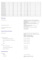
Dell 2405FPW User Manual - Page 8
DVI Connector, Pin Number, pin Side of the Connected Signal Cable - no power
 |
View all Dell 2405FPW manuals
Add to My Manuals
Save this manual to your list of manuals |
Page 8 highlights
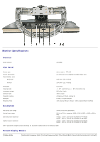
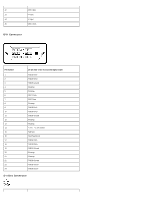
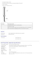
12 DDC data 13 H-sync 14 V -sync 15 DDC clock DVI Connector Pin Number 1 2 3 4 5 6 7 8 9 10 11 12 13 14 15 16 17 18 19 20 21 22 23 24 24-pin Side of the Connected Signal Cable TMDS RX2TMDS RX2+ TMDS Ground Floating Floating DDC Clock DDC Data Floating TMDS RX1TMDS RX1+ TMDS Ground Floating Floating +5V / +3.3V power Self test Hot Plug Detect TMDS RX0TMDS RX0+ TMDS Ground Floating Floating TMDS Ground TMDS Clock+ TMDS Clock- S-video Connector
-
 1
1 -
2
-
 3
3 -
 4
4 -
 5
5 -
 6
6 -
 7
7 -
 8
8 -
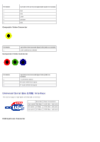 9
9 -
 10
10 -
 11
11 -
 12
12 -
 13
13 -
14
-
15
-
16
-
17
-
18
-
19
-
20
-
21
-
22
-
23
-
24
-
25
-
26
-
27
-
28
-
29
-
30
-
31
-
32
-
33
-
34
-
35
-
36
-
37
-
38
-
39
-
40
-
41
-
42
-
43
-
44
-
45
-
46
-
47
-
48
-
49
-
50
-
51
-
52
-
53
-
54
-
55
-
56
-
57
-
58
-
59
-
60
-
61
-
62
-
63
-
64
-
65
-
66
-
67
-
68
-
69
-
70
-
71
-
72
-
73
-
74
-
75
-
76
-
77
 |
 |

12
DDC data
13
H-sync
14
V-sync
15
DDC clock
DVI Connector
Pin Number
24-pin Side of the Connected Signal Cable
1
TMDS RX2-
2
TMDS RX2+
3
TMDS Ground
4
Floating
5
Floating
6
DDC Clock
7
DDC Data
8
Floating
9
TMDS RX1-
10
TMDS RX1+
11
TMDS Ground
12
Floating
13
Floating
14
+5V / +3.3V power
15
Self test
16
Hot Plug Detect
17
TMDS RX0-
18
TMDS RX0+
19
TMDS Ground
20
Floating
21
Floating
22
TMDS Ground
23
TMDS Clock+
24
TMDS Clock-
S-video Connector