Dell Force10 E300 Installing and Maintaining the E300 System - Page 10
E300 Chassis Rear View with AC Power Supplies
 |
View all Dell Force10 E300 manuals
Add to My Manuals
Save this manual to your list of manuals |
Page 10 highlights
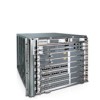
www.dell.com | support.dell.com Figure 2-2. E300 Chassis Rear View with AC Power Supplies AC Power Supply Standby Switch AC Power Supply LEDs Power Inlet Socket Air Filter fn00121a Optional Grounding Holes Figure 2-3. E300 Chassis Rear View with DC PEMs DC Power Supply Slot 0 DC Power Supply Slot 1 Air Filter fn00121cHH Optional Grounding Holes Table 2-1 lists the minimum and maximum components required to run the E300 System. 10 | The E300 System
-
 1
1 -
2
-
3
-
4
-
 5
5 -
 6
6 -
 7
7 -
 8
8 -
 9
9 -
 10
10 -
 11
11 -
 12
12 -
 13
13 -
 14
14 -
 15
15 -
16
-
17
-
18
-
19
-
20
-
21
-
22
-
23
-
24
-
25
-
26
-
27
-
28
-
29
-
30
-
31
-
32
-
33
-
34
-
35
-
36
-
37
-
38
-
39
-
40
-
41
-
42
-
43
-
44
-
45
-
46
-
47
-
48
-
49
-
50
-
51
-
52
-
53
-
54
-
55
-
56
-
57
-
58
-
59
-
60
-
61
-
62
-
63
-
64
-
65
-
66
-
67
-
68
-
69
-
70
-
71
-
72
-
73
-
74
 |
 |

10
|
The E300 System
www.dell.com | support.dell.com
Figure 2-2.
E300 Chassis Rear View with AC Power Supplies
Figure 2-3.
E300 Chassis Rear View with DC PEMs
T
able
2-
1
lists the minimum and maximum components required to run the E300 System.
Optional Grounding
Holes
AC Power Supply
AC Power Supply
LEDs
fn00121a
Air Filter
Power
Inlet Socket
Standby Switch
Optional Grounding
Holes
fn00121cHH
Air Filter
DC Power Supply
Slot 0
DC Power Supply
Slot 1