Dell Force10 E300 Installing and Maintaining the E300 System - Page 33
RPM Label and LEDs, IRC-6-IRC_COMMUP: Link to peer RPM is up
 |
View all Dell Force10 E300 manuals
Add to My Manuals
Save this manual to your list of manuals |
Page 33 highlights
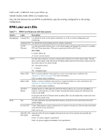
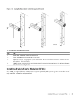
%IRC-6-IRC_COMMUP: Link to peer RPM is up %RAM-6-RAM_TASK: RPM1 is in Standby State. Once the link between the two RPMs is established, copy the running configuration to the startup configuration. RPM Label and LEDs Table 7-1. RPM Front Panel and LED Descriptions Section Management Alarms Flash Label Description Console Port Use this RJ-45 jack for the initial system boot, as well as system configuration and monitoring. Auxiliary Port Use this RJ-45 serial auxiliary port for modem connection 10/100 Ethernet Use this nonroutable Ethernet port to download images and manage the system, for example, FTP and Telnet operations. This port is provisioned with an RJ-45 jack. Port LEDs: L: Green: link is up. A: Green: activity on port Use the relay contacts to connect a remote alarm indicator to monitor alarm status. The top three contacts (next to the red bar) are for Major alarms and the bottom three contacts (next to the yellow bar) are for minor alarms. NC - Normally Closed C - Common NO - Normally Open Major LED Red: a critical condition exists (such as a severe over temperature condition). See Appendix C, Alarms, on page 57 for more information. Unlit: no major alarm conditions. Minor LED Amber: a serious condition exists (such as a single fan failure or a line card failure). See Appendix C, Alarms, on page 57 for more information. Unlit: no minor alarm conditions. ACO/LT Button Audible alarm Cut Off/Lamp Test (ACO/LT) button allows you to test the operability of LEDs to verify that they are able to light. Pressing this button temporarily illuminates the LEDs on the RPM. If you press the ACO/LT button when an alarm LED is lit, the alarm relay contacts are reset until the next alarm event. Slot Use the multimedia card (external flash memory card) slot to store and retrieve boot and system images. In Use LED Green: flash memory card is in the process of a read or write process. Do not remove the flash card when the In Use LED is lit. Unlit: not in use. PS0, PS1, PS2, Indicates if the AC power supplies (located in the rear of the chassis) are installed and PS3 LEDs operational. Green: AC power supply is operational Unlit: AC power supply not installed or not operational. Installing RPMs, Line Cards, and SFMs | 33
-
 1
1 -
2
-
3
-
4
-
5
-
6
-
7
-
8
-
9
-
10
-
11
-
12
-
13
-
14
-
15
-
16
-
17
-
18
-
19
-
20
-
21
-
22
-
23
-
24
-
25
-
26
-
27
-
 28
28 -
 29
29 -
 30
30 -
 31
31 -
 32
32 -
 33
33 -
 34
34 -
 35
35 -
 36
36 -
 37
37 -
 38
38 -
39
-
40
-
41
-
42
-
43
-
44
-
45
-
46
-
47
-
48
-
49
-
50
-
51
-
52
-
53
-
54
-
55
-
56
-
57
-
58
-
59
-
60
-
61
-
62
-
63
-
64
-
65
-
66
-
67
-
68
-
69
-
70
-
71
-
72
-
73
-
74
 |
 |
