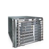
Dell Force10 E300 Installing and Maintaining the E300 System - Page 25
Installing a DC PEM, Removing the PEM Safety Cover, CAUTION
 |
View all Dell Force10 E300 manuals
Add to My Manuals
Save this manual to your list of manuals |
Page 25 highlights
Installing a DC PEM Step Task 1 Turn the remote power source (the circuit breaker panel) to the OFF position. 2 Turn the over current protector (located on the PEM front panel) to the OFF position. 3 Loosen the PEM safety cover retaining screw and remove the cover (Figure 5-3). Figure 5-3. Removing the PEM Safety Cover Status Pwr In OK MAKE GROUND CONNECTION FIRST CAUTION - Use conductors only copper CbArCAeHUaTkTUeIOrNbNGe--foTVrueerranjecocdfeef srpsWoinwagertrtuesnrogmuHirncaaeulspc.tisrccuhiat lter Always replace safety cover after servicing DsCooAuUrncoTetIOcuonNnpn-lueUgcntiwiot nhm.ilaReyeemhnaeovrvgeeizmaellodsr.euptphlayncoonnneepcotiownesr 749-00752-00 fn00118ch Step 4 5 Task (continued) Slide the PEM into power slot 0 or 1 (Figure 5-2). CAUTION: Fill all four power supply slots with power supplies or filler blanks before tightening the power supply screws. Doing this ensures that each power supply is aligned correctly. Ensure power supplies are properly aligned prior to engaging the captive screws. Doing this will reduce the likelihood of damaging screws or chassis. It may be necessary to manually align the power supplies prior to tightening. If you are only installing one PEM, replace the empty slot with two blank panels. (CC-E300-BLNK-PWR.) Start the two captive screws on each power supply by hand before tightening them all. CAUTION: Tighten the screws with a #2 Phillips screwdriver. Use no more than five inch-pounds of torque (light torque with a manual screwdriver). Use of power drivers can damage screws or chassis. Installing Power Modules | 25
-
 1
1 -
2
-
3
-
4
-
5
-
6
-
7
-
8
-
9
-
10
-
11
-
12
-
13
-
14
-
15
-
16
-
17
-
18
-
19
-
 20
20 -
 21
21 -
 22
22 -
 23
23 -
 24
24 -
 25
25 -
 26
26 -
 27
27 -
 28
28 -
 29
29 -
 30
30 -
31
-
32
-
33
-
34
-
35
-
36
-
37
-
38
-
39
-
40
-
41
-
42
-
43
-
44
-
45
-
46
-
47
-
48
-
49
-
50
-
51
-
52
-
53
-
54
-
55
-
56
-
57
-
58
-
59
-
60
-
61
-
62
-
63
-
64
-
65
-
66
-
67
-
68
-
69
-
70
-
71
-
72
-
73
-
74
 |
 |
