Dell Force10 E300 Installing and Maintaining the E300 System - Page 21
AC Power Supply Locations, Table 5-1., Optional Grounding, Holes, Air Filter, Slot 0
 |
View all Dell Force10 E300 manuals
Add to My Manuals
Save this manual to your list of manuals |
Page 21 highlights
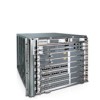
Figure 5-1. AC Power Supply Locations AC Power Supply Standby Switch AC Power Supply LEDs Slot 0 Slot 1 Slot 2 Slot 3 fn00121b Air Filter Optional Grounding Holes The E300 contains four power supply slots in the rear of the chassis (Figure 5-1). Each AC power supply contains two LEDs: Status and AC. Table 5-1 describes the LEDs. Table 5-1. AC Power Supply LEDs LED Status (upper LED) AC (lower LED) Description Green: no fault detected; unit on and functioning properly Unlit: unit not supplying power to the system; unit off or in standby mode Green: line voltage within range; operating normally; unit on or in standby mode Unlit: unit not operating or no power applied Installing Power Modules | 21
-
 1
1 -
2
-
3
-
4
-
5
-
6
-
7
-
8
-
9
-
10
-
11
-
12
-
13
-
14
-
15
-
 16
16 -
 17
17 -
 18
18 -
 19
19 -
 20
20 -
 21
21 -
 22
22 -
 23
23 -
 24
24 -
 25
25 -
 26
26 -
27
-
28
-
29
-
30
-
31
-
32
-
33
-
34
-
35
-
36
-
37
-
38
-
39
-
40
-
41
-
42
-
43
-
44
-
45
-
46
-
47
-
48
-
49
-
50
-
51
-
52
-
53
-
54
-
55
-
56
-
57
-
58
-
59
-
60
-
61
-
62
-
63
-
64
-
65
-
66
-
67
-
68
-
69
-
70
-
71
-
72
-
73
-
74
 |
 |

Installing Power Modules
|
21
Figure 5-1.
AC Power Supply Locations
The E300 contains four power supply slots in the rear of the chassis (
Figure
5-
1
).
Each AC power supply contains two LEDs: Status and AC.
T
able
5-
1
describes the LEDs.
Table 5-1.
AC Power Supply LEDs
LED
Description
Status (upper LED)
Green: no fault detected; unit on and functioning properly
Unlit: unit not supplying power to the system; unit off or in standby mode
AC (lower LED)
Green: line voltage within range; operating normally; unit on or in standby mode
Unlit: unit not operating or no power applied
Optional Grounding
Holes
AC Power Supply
AC Power Supply
LEDs
fn00121b
Air Filter
Slot 0
Slot 1
Slot 2
Slot 3
Standby Switch