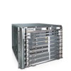
Dell Force10 E300 Installing and Maintaining the E300 System - Page 24
Removing a DC PEM, Pwr In, Status
 |
View all Dell Force10 E300 manuals
Add to My Manuals
Save this manual to your list of manuals |
Page 24 highlights
www.dell.com | support.dell.com LED Status Status Pwr In OK fn00118ch4 CC-E300-PWR-DC Status Pwr In OK Green-no fault detected Amber- under voltage Unlit-circuit not energized or circuit breaker open Green-no fault detected Amber- polarity of (+) and (-) are reversed in external cables Unlit-no power or power is under voltage Removing a DC PEM The left chassis PEM slot is labelled "0" and the right chassis PEM slot is labelled "1". For full redundancy, each PEM must be attached to a dedicated circuit breaker. For example, PEM "0" connects to circuit breaker "0" and PEM "1" connects to circuit breaker "1". WARNING: Prevent exposure and contact with hazardous voltages. Do not attempt to operate this system with the safety cover removed. Step Task 1 Switch the Over Current Protector (located on the PEM front panel) to the OFF position. 2 Turn off power to the PEM. Ensure that the remote power source is in the OFF position and that the PEM Status LED and Pwr In OK LED are off. 3 Loosen the retaining screw and remove PEM safety cover (see Figure 5-3). 4 Disconnect power cables attached to the PEM. 5 Slide the PEM out of the slot. 6 If you are not replacing the PEM, replace the empty slot with two blank panels. 24 | Installing Power Modules
-
 1
1 -
2
-
3
-
4
-
5
-
6
-
7
-
8
-
9
-
10
-
11
-
12
-
13
-
14
-
15
-
16
-
17
-
18
-
 19
19 -
 20
20 -
 21
21 -
 22
22 -
 23
23 -
 24
24 -
 25
25 -
 26
26 -
 27
27 -
 28
28 -
 29
29 -
30
-
31
-
32
-
33
-
34
-
35
-
36
-
37
-
38
-
39
-
40
-
41
-
42
-
43
-
44
-
45
-
46
-
47
-
48
-
49
-
50
-
51
-
52
-
53
-
54
-
55
-
56
-
57
-
58
-
59
-
60
-
61
-
62
-
63
-
64
-
65
-
66
-
67
-
68
-
69
-
70
-
71
-
72
-
73
-
74
 |
 |
