Dell Force10 E300 Installing and Maintaining the E300 System - Page 23
DC Requirements, Redundancy, Cable and Connector Requirements, DC PEM Locations
 |
View all Dell Force10 E300 manuals
Add to My Manuals
Save this manual to your list of manuals |
Page 23 highlights
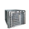
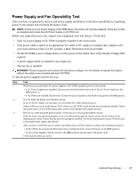
Figure 5-2. DC PEM Locations DC Power Supply Slot 0 DC Power Supply Slot 1 fn00121cHH Air Filter DC Requirements Maximum Power Dissipation Maximum DC PEM Input Current Optional Grounding Holes 2400W 60A Redundancy For full facility redundancy, install two DC PEMs where each PEM must be attached to an independent power source with a dedicated circuit breaker sized in accordance with your local building and electrical safety codes. Cable and Connector Requirements You must provide your own cables to connect to a remote power source (a circuit breaker panel, for example) in your equipment rack or facility. Cables must be sized to meet the following criteria: • Rated for 60A service to allow for a fully loaded E300 system per NEC in the United States or internationally, per local safety codes. • Limit voltage drop across the cable length to 0.5V or less. Before you make the cable connections, apply a coat of anti-oxidant paste to unplated metal contact surfaces. File unplated connectors, braided straps, and bus bars to a shiny finish. It is not necessary to file and coat tinned, solder-plated, or silver-plated connectors or other plated connection surfaces, such as those on the PEM studs. NOTE: Please take precautions against over-tightening the screws or nuts on this device. Installing Power Modules | 23
-
 1
1 -
2
-
3
-
4
-
5
-
6
-
7
-
8
-
9
-
10
-
11
-
12
-
13
-
14
-
15
-
16
-
17
-
 18
18 -
 19
19 -
 20
20 -
 21
21 -
 22
22 -
 23
23 -
 24
24 -
 25
25 -
 26
26 -
 27
27 -
 28
28 -
29
-
30
-
31
-
32
-
33
-
34
-
35
-
36
-
37
-
38
-
39
-
40
-
41
-
42
-
43
-
44
-
45
-
46
-
47
-
48
-
49
-
50
-
51
-
52
-
53
-
54
-
55
-
56
-
57
-
58
-
59
-
60
-
61
-
62
-
63
-
64
-
65
-
66
-
67
-
68
-
69
-
70
-
71
-
72
-
73
-
74
 |
 |
