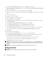
Dell Inspiron 1300 Owner's Manual - Page 18
Bottom View, Memory, Wireless Mini PCI Card, CD/DVD Drive, Hard Drive, Using a Battery
 |
View all Dell Inspiron 1300 manuals
Add to My Manuals
Save this manual to your list of manuals |
Page 18 highlights
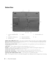
Bottom View 1 2 3 8 7 1 memory module/Mini PCI cover 2 optical drive locking screw 3 hard drive cover 65 4 4 battery 5 battery-bay latch lock 6 battery-bay latch release 7 thermal module cover 8 fan M E M O R Y M O D U L E / M I N I P C I C O V E R - Covers the compartment that contains the memory module(s) and Mini PCI card. For more information on replacing memory, see "Memory." For more information on replacing the Mini PCI card, see "Wireless Mini PCI Card." O P T I C A L D R I V E L O C K I N G S C R E W - Secures the optical drive in the optical drive bay. For more information, see "CD/DVD Drive." H A R D D R I V E - Stores software and data. For more information, see "Hard Drive." B A T T E R Y - When a battery is installed, you can use the computer without connecting the computer to an electrical outlet. For more information, see "Using a Battery." B A T T E R Y - B A Y L A T C H L O C K - Unlocks the battery so that it can be released from the battery bay. B A T T E R Y - B A Y L A T C H R E L E A S E - Releases the battery from the battery bay. See "Replacing the Battery." P R O C E S S O R A N D T H E R M A L M O D U L E C O V E R - Covers the processor and thermal module. F A N - The computer uses fans to create airflow through the vents, which prevents the computer from overheating. 18 A Tour of Your Computer
-
 1
1 -
2
-
3
-
4
-
5
-
6
-
7
-
8
-
9
-
10
-
11
-
12
-
 13
13 -
 14
14 -
 15
15 -
 16
16 -
 17
17 -
 18
18 -
 19
19 -
 20
20 -
 21
21 -
 22
22 -
 23
23 -
24
-
25
-
26
-
27
-
28
-
29
-
30
-
31
-
32
-
33
-
34
-
35
-
36
-
37
-
38
-
39
-
40
-
41
-
42
-
43
-
44
-
45
-
46
-
47
-
48
-
49
-
50
-
51
-
52
-
53
-
54
-
55
-
56
-
57
-
58
-
59
-
60
-
61
-
62
-
63
-
64
-
65
-
66
-
67
-
68
-
69
-
70
-
71
-
72
-
73
-
74
-
75
-
76
-
77
-
78
-
79
-
80
-
81
-
82
-
83
-
84
-
85
-
86
-
87
-
88
-
89
-
90
-
91
-
92
-
93
-
94
-
95
-
96
-
97
-
98
-
99
-
100
-
101
-
102
-
103
-
104
-
105
-
106
-
107
-
108
-
109
-
110
-
111
-
112
-
113
-
114
-
115
-
116
-
117
-
118
-
119
-
120
-
121
-
122
-
123
-
124
-
125
-
126
-
127
-
128
-
129
-
130
-
131
-
132
-
133
-
134
-
135
-
136
-
137
-
138
-
139
-
140
-
141
-
142
 |
 |
