Dell OptiPlex Gs Service Manual (.pdf) - Page 28
System Board, Main Memory
 |
View all Dell OptiPlex Gs manuals
Add to My Manuals
Save this manual to your list of manuals |
Page 28 highlights
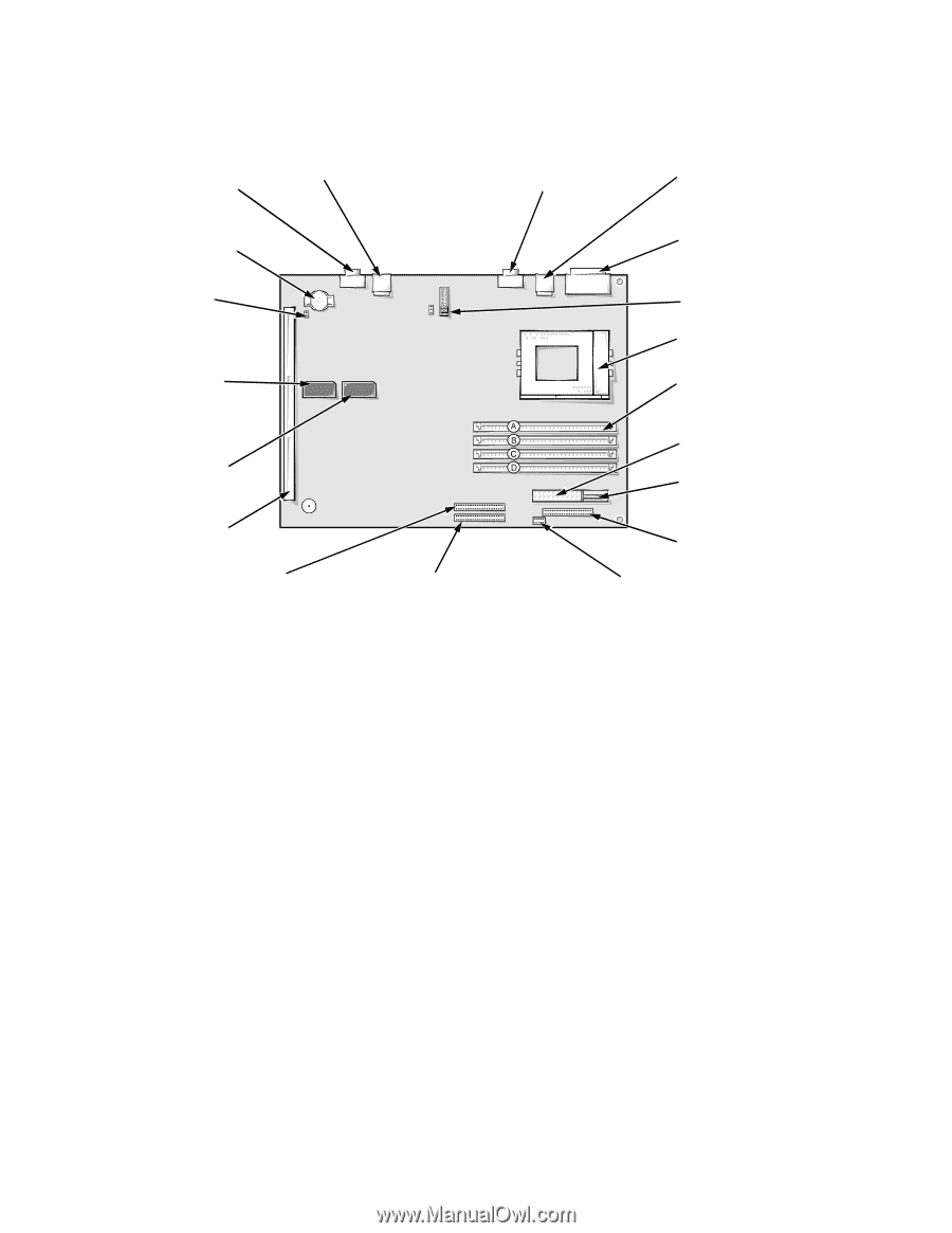
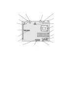
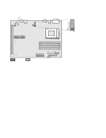
System Board The subsections that follow provide service-related information about some system board components. Figure 1-14 shows the system board layout. video connector (MONITOR) battery socket (BATTERY) NICRST jumper NIC connector (ENET) serial port 2 connector (SERIAL2) keyboard/mouse connectors (stacked) (KYBD/MOUSE) serial port 1/parallel port connectors (stacked) (PARALLEL/SERIAL1) jumpers video memory socket (VMEM2) video memory socket (VMEM1) riser board connector (RISER) front of computer primary EIDE interface secondary EIDE interface connector (IDE1) connector (IDE2) microprocessor socket (MICROPROCESSOR) SIMM sockets (4) (SIMM_A through SIMM_D) main power input connector (POWER1) 3.3-V power input connector (POWER2) diskette/tape drive interface connector (DSKT) control panel connector (PANEL) Figure 1-14. System Board Components Main Memory The four SIMM sockets on the system board can accommodate combinations of 4-, 8-, 16-, and 32-MB SIMMs up to a total memory capacity of 128 MB. The standard main memory is 8 MB of high-speed (60-ns) EDO SIMMs. The SIMMs must be installed in pairs of the same capacity. Sockets SIMM_A and SIMM_B must always have SIMMs installed. See "SIMMs" in Chapter 4 or 5, as appropriate for your system, for information on removing and replacing SIMMs. 1-16 Dell OptiPlex Gs and Gs+ Systems Service Manual
-
 1
1 -
2
-
3
-
4
-
5
-
6
-
7
-
8
-
9
-
10
-
11
-
12
-
13
-
14
-
15
-
16
-
17
-
18
-
19
-
20
-
21
-
22
-
 23
23 -
 24
24 -
 25
25 -
 26
26 -
 27
27 -
 28
28 -
 29
29 -
 30
30 -
 31
31 -
 32
32 -
 33
33 -
34
-
35
-
36
-
37
-
38
-
39
-
40
-
41
-
42
-
43
-
44
-
45
-
46
-
47
-
48
-
49
-
50
-
51
-
52
-
53
-
54
-
55
-
56
-
57
-
58
-
59
-
60
-
61
-
62
-
63
-
64
-
65
-
66
-
67
-
68
-
69
-
70
-
71
-
72
-
73
-
74
-
75
-
76
-
77
-
78
-
79
-
80
-
81
-
82
-
83
-
84
-
85
-
86
-
87
-
88
-
89
-
90
-
91
-
92
-
93
-
94
-
95
-
96
-
97
-
98
-
99
-
100
-
101
-
102
-
103
-
104
-
105
-
106
-
107
-
108
-
109
-
110
-
111
 |
 |