Dell OptiPlex Gs Service Manual (.pdf) - Page 66
System Board Components,
 |
View all Dell OptiPlex Gs manuals
Add to My Manuals
Save this manual to your list of manuals |
Page 66 highlights
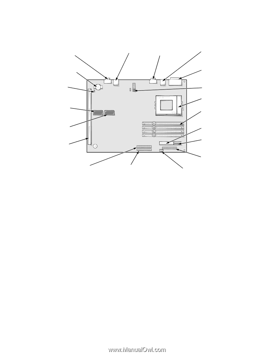
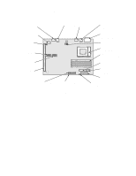
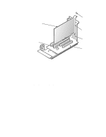
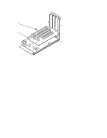
System Board Components The subsections that follow Figure 4-10 contain procedures for removing system board and riser board components. video connector (MONITOR) NIC connector (ENET) serial port 2 connector (SERIAL2) keyboard/mouse connectors (stacked) (KYBD/MOUSE) battery socket (BATTERY) NICRST jumper video memory socket (VMEM2) video memory socket (VMEM1) riser board connector (RISER) serial port 1/parallel port connectors (stacked) (PARALLEL/SERIAL1) jumpers microprocessor socket (MICROPROCESSOR) SIMM sockets (4) (SIMM_A through SIMM_D) main power input connector (POWER1) 3.3-V power input connector (POWER2) front of computer primary EIDE connector secondary EIDE connector (IDE1) (IDE2) diskette/tape drive interface connector (DSKT) control panel connector (PANEL) Figure 4-10. System Board Components 4-12 Dell OptiPlex Gs and Gs+ Systems Service Manual
-
 1
1 -
2
-
3
-
4
-
5
-
6
-
7
-
8
-
9
-
10
-
11
-
12
-
13
-
14
-
15
-
16
-
17
-
18
-
19
-
20
-
21
-
22
-
23
-
24
-
25
-
26
-
27
-
28
-
29
-
30
-
31
-
32
-
33
-
34
-
35
-
36
-
37
-
38
-
39
-
40
-
41
-
42
-
43
-
44
-
45
-
46
-
47
-
48
-
49
-
50
-
51
-
52
-
53
-
54
-
55
-
56
-
57
-
58
-
59
-
60
-
 61
61 -
 62
62 -
 63
63 -
 64
64 -
 65
65 -
 66
66 -
 67
67 -
 68
68 -
 69
69 -
 70
70 -
 71
71 -
72
-
73
-
74
-
75
-
76
-
77
-
78
-
79
-
80
-
81
-
82
-
83
-
84
-
85
-
86
-
87
-
88
-
89
-
90
-
91
-
92
-
93
-
94
-
95
-
96
-
97
-
98
-
99
-
100
-
101
-
102
-
103
-
104
-
105
-
106
-
107
-
108
-
109
-
110
-
111
 |
 |